Comelit 1404 Manual técnico - Página 6
Procurar online ou descarregar pdf Manual técnico para Interruptor Comelit 1404. Comelit 1404 18 páginas. Digital switching device for simplebus 2 system
To set TOP 3 mode:
1. Position the S3 DIP-switches as follows: DIP1-OFF and DIP2-ON.
2. Define the range of ZONES managed by the switching device, via S1, S2 and DIP3 of S3:
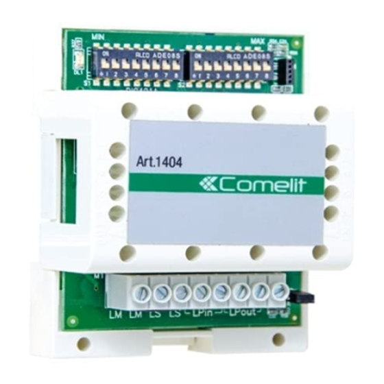
S1 defines the minimum value MIN of the range (see table
S2 defines the maximum value MAX of the range (see table
DIP3 of S3 defines the zone addresses managed:
•
OFF for zone addresses from 1 to 250 (default)
•
ON for zone addresses from 251 to 500
The switching device should be used to wire all the main external units in the part of the system feeding into the terminals
LPin-LPin of switching devices Art. 1404 in TOP 1 mode.
Switching device Art. 1404 in TOP 3 mode manages the ZONES falling within the set range.
The range can be EXTENDED (from 1 to 500 by setting the dip switches of S1 to OFF, the dip switches of S2 to ON and DIP 3
of S3 to OFF) or LIMITED but only in intervals between 1 and 250 (by setting the MIN range on S1, the MAX range on S2 and
DIP 3 of S3 to OFF) or from 251 to 500 (by setting the MIN range on S1, the MAX range on S2 and DIP 3 of S3 to ON).
Only external units in TOP mode can be wired to the TOP 3 switching device.
Self activation CANNOT be managed via wired ports on the LPin-LPin input of switching device Art. 1404.
CAUTION! Separate switching devices must manage code ranges which are not overlapping.
Examples:
MODE
STANDARD
TOP 1
TOP 3
Special programming
For each of the previous 4 modes the following is also possible:
•
Bus line cascade distribution
f JP1 should be left in position A only on the last switching device.
•
management of connection on the LS line useful for distributing the video signal in cascade over TOP systems, also
without requiring one or more secondary external units.
f If there is no secondary external unit, set DIP4 of S3 to ON provide power over LS via Art. 1209 or 1210/1210A.
RANGE 1÷10
ZONE 2
EXTENDED RANGE
1-500
ZONE 2÷10
ZONE 300÷400
"Programming table for dip-switches and S3
"Programming table for dip-switches and S3
EXAMPLES
ON
1 2 3 4
ON
ON
1 2 3 4
1 2 3 4
5
6 7
8
ON
1 2 3 4
ON
1 2 3 4
ON
1 2 3 4
MIN
MAX
ON
ON
1 2 3 4
5
6 7
8
1 2 3 4
5
6 7
8
ON
ZONE 260
1 2 3 4
ON
ON
1 2 3 4
5
6 7
8
1 2 3 4
5
6 7
8
ON
ON
1 2 3 4
5
6 7
8
1 2 3 4
5
6 7
8
ON
ON
1 2 3 4
5
6 7
8
1 2 3 4
5
6 7
8
setting").
setting").
ON
1 2 3 4
5
6 7
8