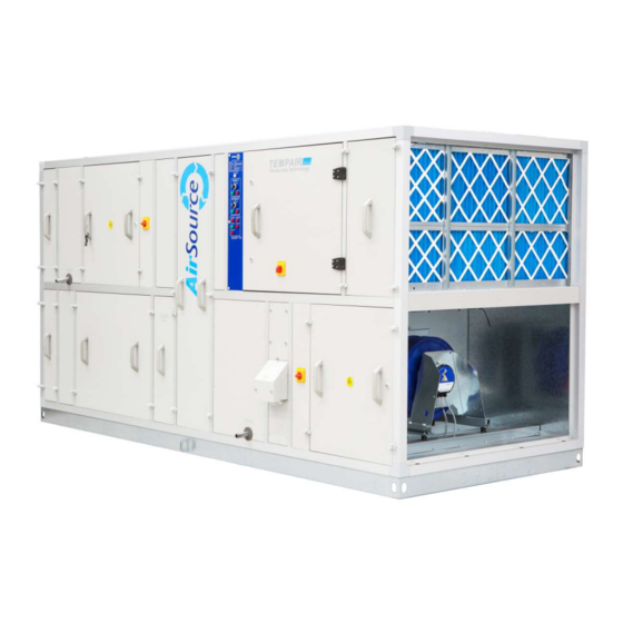
AirSource TempAir Manual de Instruções de Instalação, Operação e Manutenção - Página 11
Procurar online ou descarregar pdf Manual de Instruções de Instalação, Operação e Manutenção para Manipuladores de ar AirSource TempAir. AirSource TempAir 20 páginas. Air handling units, airsource heatpumps

Condensate
Drains
All condensate drains on the AHU require a suitable
All condensate drains on the AHU require a suitable trap. Drain locations are shown
our drawing. It is important to select the correct type and depth of trap otherwise a
build-up of condensate may occur
water prior to start-up.
It is recommended to
use large radius swept
use large radius swept
bends to avoid air
locks. Ensure all pipes,
locks. Ensure all pipes,
including drain
connections from the
A.H.U. fall to drain.
COMMISSIONING
SIONING & TESTING
General
All units require airside commissioning on site.
All units require airside commissioning on site. The fans should be operated in hand
to commission the air volume.
to commission the air volume.
Fans
Pre-Start Checks
After assembly of the AHU
General Arrangement drawing for specific details. Isolate electric supply to f
General Arrangement drawing for specific details. Isolate electric supply to f
General Arrangement drawing for specific details. Isolate electric supply to fan-motor
before entering the fan section.
before entering the fan section.
Check for any visible damage to the fan impeller and mounting assembly
Check for any visible damage to the fan impeller and mounting assembly
Check for any visible damage to the fan impeller and mounting assembly
Check that anti-vibration mountings are level and that bolts are tight
Check motor terminal cover is secure and that bolts are tight.
Check motor terminal cover is secure and that bolts are tight.
Ensure all left over installation materials and other foreign objects have
been removed from the fan cavity.
been removed from the fan cavity.
Test Run
Test run the motor and drive to ensure that the fan is rotating in the correct direction
Test run the motor and drive to ensure that the fan is rotating in the correct direction
Test run the motor and drive to ensure that the fan is rotating in the correct direction
as identified by the arrow on the fan scroll. If the rota
as identified by the arrow on the fan scroll. If the rotation is in reverse, stop th
and reverse any two incoming supply lines to the motor or starter (3 phase supply).
Check that the current being drawn by the motor does not exceed
Check that the current being drawn by the motor does not exceed the motor full load
current. Note! All access panels must be closed durin
. Note! All access panels must be closed during this test, otherwise false
readings will be obtained.
readings will be obtained.
Speed
Follow the instructions in the manual for the inverter. Check rotational d
Follow the instructions in the manual for the inverter. Check rotational d
Follow the instructions in the manual for the inverter. Check rotational direction and
Controlled change polarity of electrical supply by reversing any two incoming supply lines to the
polarity of electrical supply by reversing any two incoming supply lines to the
polarity of electrical supply by reversing any two incoming supply lines to the
Fans
motor to change direction if required. Set the inverter frequency as indicated on the
motor to change direction if required. Set the inverter frequency as indicated on the
motor to change direction if required. Set the inverter frequency as indicated on the
AHU general arrangement drawing.
HU general arrangement drawing.
Packaged If the unit is complete with a factory provided control panel and the fan directions are
If the unit is complete with a factory provided control panel and the fan directions are
If the unit is complete with a factory provided control panel and the fan directions are
Controls
incorrect, it is recommended that the polarity of the unit be changed at the incoming mains.
incorrect, it is recommend
This will then keep other equipment such as compressors in synchronisation. The unit will be
This will then keep other equipment such as compressors in synchronisation. The unit will be
This will then keep other equipment such as compressors in synchronisation. The unit will be
provided with a specific wiring diagram located in the control panel. A controls philosophy will
provided with a specific wiring diagram located in the control panel. A controls philosophy will
provided with a specific wiring diagram located in the control panel. A controls philosophy will
also be provided to the contractor.
also be provided to the contractor.
. It is important to select the correct type and depth of trap otherwise a
. It is important to select the correct type and depth of trap otherwise a
f condensate may occur. IMPORTANT: Ensure that the trap is charged with
.
AHU, the following checks should be made. Refer to
, the following checks should be made. Refer to data chart on
vibration mountings are level and that bolts are tight
vibration mountings are level and that bolts are tight
l left over installation materials and other foreign objects have
l left over installation materials and other foreign objects have
incoming supply lines to the motor or starter (3 phase supply).
incoming supply lines to the motor or starter (3 phase supply).
ed that the polarity of the unit be changed at the incoming mains.
trap. Drain locations are shown on
trap is charged with
The fans should be operated in hand
tion is in reverse, stop the motor
the motor full load
g this test, otherwise false
Installation, Operation & Maintenance Manual
stallation, Operation & Maintenance Manual
10
