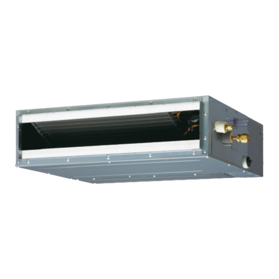
AirStage ARXD18GALH Manual de instalação - Página 18
Procurar online ou descarregar pdf Manual de instalação para Ar condicionado AirStage ARXD18GALH. AirStage ARXD18GALH 20 páginas. Indoor unit (duct type)

7.2. Custom code setting
Selecting the custom code prevents the indoor unit mix-up.
(Up to 4 codes can be set.)
Perform the setting for both the indoor unit and the remote controller.
Confusion
Indoor
unit
Remote
controller
Custom code setting for indoor unit
Set the DIP switch SET 3 SW1, SW2 referring to the Table B.
ON
OFF
SW
SW
1
2
Table B
A (Factory setting)
DIP switch SET3 SW1
DIP switch SET3 SW2
7.3. Static pressure mode
If the applicable static pressure does not match the static pressure mode, the static
pressure mode may be changed to another mode manually.
RECOMMENDED RANGE OF
EXTERNAL STATIC PRESSURE
AR04/07/09/12/14/18 0Pa to 90Pa
It is necessary to set up a static pressure mode for each usage of static pressure.
Static pressure can be set at site.
Relation between set values and static pressure are as the following table.
• FUNCTION SETTING can be performed with the wired or wireless remote controller.
(The remote controller is optional equipment)
• Refer to the wired or wireless remote controller manual for detailed setting information.
Function Number
Setting Number
26
Setting static pressure becomes "50Pa" if AR24 is set to "06" through "09".
En-17
Code change
A
B
C
A
B
C
Dip switch "SET 3"
SW
SW
3
4
Custom code
B
OFF
ON
OFF
OFF
OFF
CAUTION
AR24 0Pa to 50Pa
Setting Static Pressure
00
0 Pa
01
10 Pa
02
20 Pa
03
30 Pa
04
40 Pa
05
50 Pa
06
60 Pa (50 Pa)
07
70 Pa (50 Pa)
08
80 Pa (50 Pa)
09
90 Pa (50 Pa)
31
25 Pa (Factory setting)
7.4. Switching of drainage function
If contained drain pump is not used, set the drainage function to "Invalid" in the drainage
function switching.
• If contained drain pump is not use:
When used under "WALL MOUNTED TYPE/FLOOR STANDING CONCEALED
TYPE".
D
When used in natural drainage under "CEILING CONCEALED TYPE".
• Installation method
Set the DIP switch SET 4 SW1, SW1 referring to the Table C.
D
Table C
DIP switch
SET 4 SW1
7.5. Switching of airfl ow direction louver function
When auto louver grille (Optional parts) is attached, set the airfl ow direction louver func-
tion "Valid".
C
D
The airfl ow direction louver of auto louver grille can be operated by the remote controller
ON
while the airfl ow direction louver function is valid.
ON
ON
•
Installation method
Set the DIP switch SET 4 SW2, SW2 referring to the Table D.
Table D
DIP switch
SET 4 SW2
ON
DIP switch "SET 4"
OFF
SW SW SW SW
1
2
3
4
OFF
Drainage function "Valid" (Factory setting)
ON
Drainage function "Invalid"
ON
DIP switch "SET 4"
OFF
SW SW SW SW
1
2
3
4
Airflow direction louver function "Invalid"
OFF
(Factory setting)
ON
Airflow direction louver function "Valid"
