Draper Silhouette/Series E Instruções de instalação e funcionamento - Página 4
Procurar online ou descarregar pdf Instruções de instalação e funcionamento para Ecrã de projeção Draper Silhouette/Series E. Draper Silhouette/Series E 5 páginas. Electric projection screen
Também para Draper Silhouette/Series E: Instruções de instalação e funcionamento (5 páginas)

220V Silhouette/Series E & V by Draper
121
mm
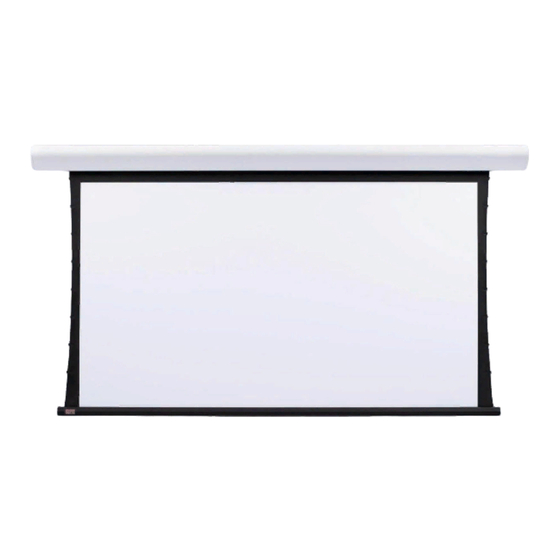
Series E Viewing Surface Shown; Series V with Tab Tensioning also available.
At left, Series V slat bar is depicted inside case. Series E has a typical round bottom dowel. For all Silhouettes, the dowel is concealed inside the case.
Wiring Diagrams—220V Motor and Quiet Motor
Single Station Control
CE Approved
Junction box at
left end of screen
Internal Screen Wiring
Blue-220v (Common)
Brown-220v (Down)
Black-220v (Up)
Green/Yellow (Motor Ground)
Control
switch
Dashed wiring
by installer
220v,
50 Hz.
Case Dimensions
Silhouette
D
152
Series E
13.5 cm
mm
Series V
Varies
Wiring Diagrams
Please Note: Do not wire motors in parallel.
Multiple Station Control
Junction box at
Not CE Approved
left end of screen
Internal Screen Wiring
Blue-220v (Common)
Brown-220v (Down)
Black-220v (Up)
Green/Yellow (Motor Ground)
Cap off with wire
nut & tape
Red
Blue
Black
Red
Blue
Black
Red
Blue
Black
Dashed wiring
by installer
220v, 50 Hz.
Wiring Diagrams—Plug & Play 220V Motor
with Built-in Low Voltage Controller
Single Low Voltage Control
Internal Screen Wiring
White (Neutral)
Black
Green (Ground)
Data Cable
Wall Switch,
RF or IR
Receiver,
or integrated
control system
220V
www.draperinc.com
22 mm holes for supply wires located on back
and top, 64 mm from left end of case.
D
Viewing Surface
Wiring Diagrams—220V Motor and Quiet Motor
with Built-in Low Voltage Controller
Single Station Control
CE Approved
Junction box at
left end of screen
Internal Screen Wiring
Blue-220v (Common)
Brown-220v (Down)
Black-220v (Up)
Green (Motor Ground)
Data Cable
220v,
50 Hz.
Dashed wiring
Wall Switch,
by installer
RF or IR
Receiver,
or integrated
control system
Multiple Low Voltage Controls
Internal Screen Wiring
White (Neutral)
Black
Green (Ground)
Data
Cables
Wall Switches,
RF or IR
Receivers,
or integrated
220V
control systems
(765) 987-7999
Page 4 of 5
Multiple Station Control
Junction box at
Not CE Approved
left end of screen
Internal Screen Wiring
Blue-220v (Common)
Brown-220v (Down)
Black-220v (Up)
Green (Motor Ground)
Data
Cables
220v, 50 Hz.
Wall Switches,
RF or IR
Receivers,
or integrated
control systems
