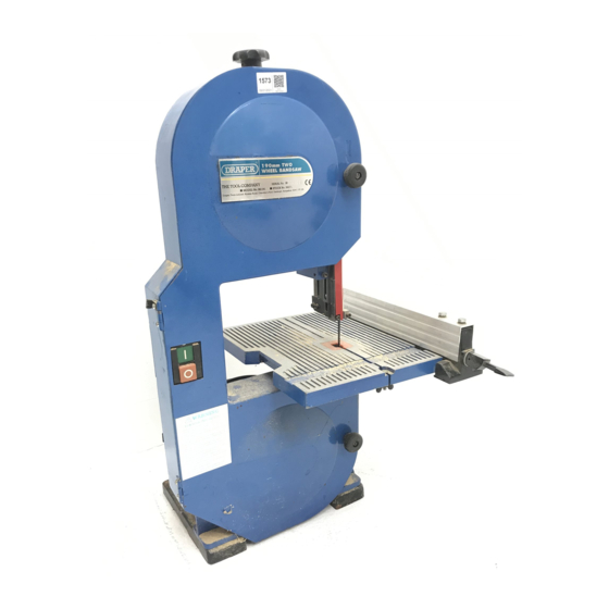
Draper BS190 Manual de instruções - Página 16
Procurar online ou descarregar pdf Manual de instruções para Serra Draper BS190. Draper BS190 20 páginas. Two wheel bandsaw
Também para Draper BS190: Manual de instruções de utilização (20 páginas)

USE OF ACCESSORIES
MITRE GUIDE
Fig.32.
Most cross cut work, especially with small pieces of
material are more easily controlled with the use of
the mitre guide. The mitre guide is also used for
accurate mitre and compound cuts. The guide is
graduated to 45˚ for assistance in cutting both left
and right hand angles. Fig.32.
Fig.33.
RIP FENCE
True straight line rip cutting is best done by guiding
the work against the rip fence. The fence can also be
used for cutting off exact widths. Fig.33.
WARNING: The supporting surface where the band
saw is mounted, should be examined carefully after
Fig.34.
mounting to ensure that there is no movement during
use. If any tipping or walking is noted, secure the
workbench or supporting surface before operating
12mm DIAMETER
bandsaw.
(4) HOLES
110mm
MOUNTING BANDSAW TO WORKBENCH
If the bandsaw is to be used in a permanent location,
it should be fastened securely to a firm supporting
surface such as a workbench.
240mm
If mounting to a workbench, holes should be drilled
through the supporting surface of the workbench
using dimensions illustrated. Fig.34.
Fig.35.
1.Each leg should be bolted down securely using
10mm diameter machine bolts, lockwashers and
10mm hex. nuts (not included). Bolt length should be
45mm plus the thickness of the bench top.
2.Locate and mark the holes where the bandsaw is to
be mounted.
3.Drill four 12mm diameter holes through the
workbench.
4.Place the bandsaw on the workbench aligning the
holes in the feet with the holes drilled in the
"C " Clamp
workbench.
"C " Clamp
Base
5.Insert all four 10mm bolts and tighten.
NOTE: All bolts should be inserted from the top.
Install the washers and nuts from the underside of the
bench.
Workbench
CLAMPING BANDSAW TO WORKBENCH
The bandsaw can be clamped to a workbench using
two (2) or more "C" clamps on base of unit. Fig.35.
- 16 -
