Draper DA150/300B Manual de instruções - Página 9
Procurar online ou descarregar pdf Manual de instruções para Compressor de ar Draper DA150/300B. Draper DA150/300B 16 páginas. 100, 150 & 200 litre compressors

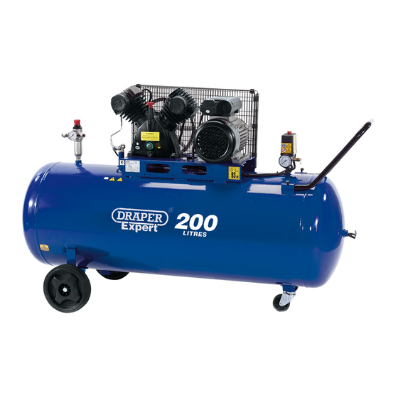
OVERLOAD CUT-OUT (Fig.7):
The compressor is equipped with an overload
cut-out (G) which operates as a safety device
to protect the motor. The device will activate in
case of motor overload or overheating due to
operation troubles. In this case, the safety
device will automatically activate,
disconnecting the compressor and avoiding
possible motor damages.
To restart the compressor, proceed as follows:
- Allow three minutes.
- Position the pressure switch to"0" OFF.
- Manually reset the thermal cut-out.
- Position the pressure switch to "1" ON.
If you restart the compressor and the overload
cut-out releases again, turn the main switch to
position "0" OFF, unplug the equipment and
contact the Authorized Service Centre.
If disconnection is required from the air tap
assembly, ensure the tap is fully closed to stop
air loss from the tank.
NOTE: After reconnection is complete,
ensure that the tap is opened again.
It is essential to connect air line, air filter
separator and lubricator to ensure a good,
clean air supply is provided for the tool.
(NOTE: If the intended tool for use is a spray
gun, use only a filter separator as
lubrication will cause contamination of the
material being sprayed).
Draper Stock No.51857 - Air Filter,
Regulator & Lubricator.
Draper Stock No.51858 - Air Filter &
Regulator.
To ensure an optimum air supply, please
refer and carry out the following procedures
as recommended
Some of the operations listed in this section will require the compressor to be returned to an
Authorized Service Agent.
Before carrying out any service or routine operation to your compressor, ensure the power
has been disconnected and all pressure has been released from the tank, so as to prevent
any sudden unexpected restart. After any maintenance operation, make sure all components
have been fitted correctly.
OPERATION AND USE
MAINTENANCE
- 8 -
Fig.7.
(G)
