BD Sensors AX16-DM01 Manual de instruções
Procurar online ou descarregar pdf Manual de instruções para Instrumentos de medição BD Sensors AX16-DM01. BD Sensors AX16-DM01 2 páginas. Digital gauge
EN
Operating Manual
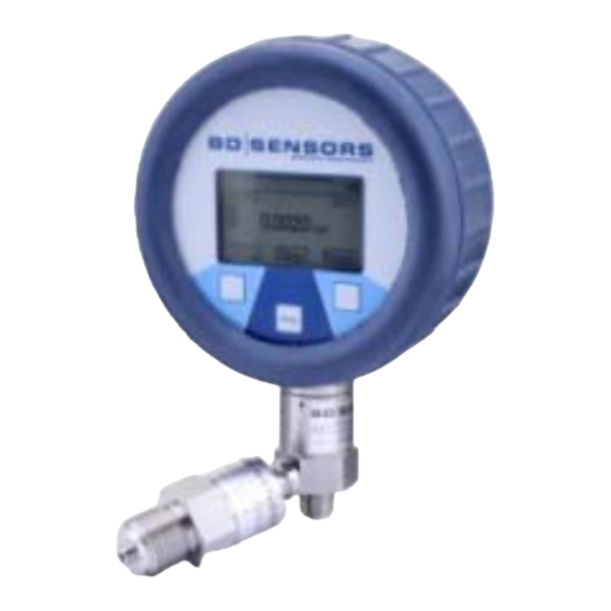
Digital gauge DM01, DM01-500, DM01-500 HD
DM01
www.bdsensors.com
Headquarters
Eastern Europe
BD SENSORS GmbH
BD SENSORS s.r.o.
BD-Sensors-Str. 1
Hradištská 817
D - 95199 Thierstein
CZ - 687 08 Buchlovice
Germany
Czech Republic
Tel.: +49 (0) 9235-9811-0
Tel.: +42 (0) 572-4110 11
Fax: +49 (0) 9235-9811-11
Fax: +42 (0) 572-4114 97
Russia
China
BD SENSORS RUS
BD SENSORS China Co, Ltd.
39a, Varshavskoe shosse
Room B, 2nd Floor, Building 10, No.
RU - Moscow 117105
1188 Lianhang Rd.
201112 Shanghai,
Russia
China
Tel.: +7 (0) 95-380 1683
Tel.: +86 (0) 21-51600 190
Fax: +7 (0) 95-380 1681
Fax: +86 (0) 21-33600 613
Further agencies in:
EUROPA
• Belgien
• Rumänien
• Dänemark
• Schweden
• England
• Schweiz
• Finnland
• Slowakei
• Frankreich
• Spanien
• Griechenland
• Türkei
• Italien
• Ukraine
• Litauen
• Luxemburg
AFRIKA
• Niederlande
• Ägypten
• Norwegen
• Südafrika
• Polen
• Portugal
The addresses of our distribution partners are listed on our
homepage www.bdsensors.com. It is possible to download data
sheets, operating manuals, ordering codes and certificates, as
well.
1. General information
1.1 Information on the operating manual
This operating manual contains important information on proper
usage of the device. Read this operating manual carefully before
installing and starting up the pressure measuring device.
Adhere to the safety notes and operating instructions which are
given in the operating manual. Additionally applicable regulations
regarding occupational safety, accident prevention as well as
national installation standards and engineering rules must be
complied with!
For the installation, maintenance and cleaning of the device,
you must absolutely observe the relevant regulations and
stipulations on explosion protection (VDE 0160, VDE 0165 or EN
60079-14) as well as the occupational safety provisions.
The device was constructed acc. to standards
EN60079-0:2009, EN60079-11:2012.
This operating manual is part of the device and must be kept at
a, for the personnel always accessible location, close to the
installation position of the device.
This operating manual is copyrighted. The contents of this
operating manual reflect the version available at the time of
printing. It has been issued to our best knowledge and belief.
However, errors may have occurred. For incorrect statements
and their consequences, liability cannot be assumed by BD
SENSORS.
– Technical modifications reserved –
1.2 Symbols used
DANGER! – Dangerous situation, which may result in
serious or fatal injuries
WARNING! – Potentially dangerous situation, which may
result in fatal or serious injuries
CAUTION! – Potentially dangerous situation, which may
result in minor injuries
!
CAUTION! – Potentially dangerous situation, which may
result in damage of objects
NOTE – Tips and information for the user to ensure
good conditions for the operation.
1.3 Target group
WARNING! To avoid hazards for the operator and
damages
instructions have to be worked out by qualified
technical personnel.
1.4 Limitation of liability
No liability is assumed and warranty claims are excluded in case
of non-observance of the operating manual, improper application,
modification of or damage to the device.
1.5 Intended use
- The battery powered digital gauge has been designed for
extremely high demands in the sector of calibration and test
technology. It can be easily and quickly installed in situ.
- It is in the responsibility of the user to verify whether the
chosen device is suitable for the intended application. In
case of any doubts, contact our sales department to
eliminate any indistinctness. BD SENSORS does not
assume any liability for an incorrect selection and its
consequences!
-
Permissible media are gases or liquids, which are compati-
ble with the media wetted parts described in the data sheet.
In addition it has to be ensured, that this medium is com-
patible with the media wetted parts.
- The technical data listed in the current data sheet are en-
gaging. If the data sheet is not available, please order or
download it from our homepage.
(http://www.bdsensors.com)
WARNING! - Danger through improper usage!
WARNING! - Danger by not designated use. By any
changes, as for example: unscrewing the battery case cap,
the decreasing of the protection screwing of the communi-
cation interface, device may not be used in explosive at-
mospheres.
WARNING! - The operation of the communication interface
is not allowed in the explosive atmospheres.
WARNING! - Battery operation: Use only the prescribed
batteries!
1.6 Safety technical maximum values
AX16-DM01, AX16-DM01-500, AX16-DM01-500 HD:
zone 1: II 2G Ex ia IIC T4 Gb
Permissible temperature: -10 ... 55°C
Supply: 3x 1.5 V / AA: Duracell Plus Power batteries
1.7 Package contents
Please verify that all listed parts are undamaged included in the
delivery and check for consistency specified in your order.
The batteries are already used. The circuit is interrupted by an
ASIEN
insulation foil. Take this before first introduction, see in addition
• Indien
battery change!
• Iran
• Israel
1.8 UL – Approval (for equipment with UL-identification)
• Japan
The UL – Approval was done with respect to U.S. standards
norms which also correspond with the applicable Canadian
• Kasachstan
standards norms for safety.
• Korea
Note the following points, so that devices fulfils the demands of
• Malaysia
UL approval:
• Singapur
- The transmitter shall be supplied by Limited Energy Source
• Taiwan
(per UL 61010) or NEC Class 2 Power Source.
• Thailand
- only indoor use
• Vietnam
- maximum operating voltage: see technical data
- use only batteries with UL certification
AUSTRALIEN
2. Product identification
The manufacturing label serves for the identification of the device
for the display and the pressure transmitter module. It provides
the most important data. By the ordering code, the product can
be clearly identified.
Serialnumber
Ordering code
Type designation
Supply
Ex-designation and
number of EC type
examination
certificate
Serialnumber
Ordering code
Type designation
Input
Fig. 1 Manufacturing label
!
The manufacturing label must not be removed from the
device!
3. Mechanical Installation
3.1 Mounting and safety instructions
Warning: Operation of the display AX16-DM01 with the EC-
Type Examination certificate IBExU12ATEX1108 X is per-
mitted only in combination with the accompanying pressure
transmitter with the EC-Type Examination certificate
IBExU10ATEX 1026U
Warning! If both equipments have not been used in the
scheduled
transmitter with certificate IBExU10 ATEX 1026 U), then the
complete system has to be put immediately out of opera-
tion! A potentially damage of one or both devices could
have been occurred! The device(s) consequently lose the
IS-certification when using not for intended purpose.
WARNING! Mount the device (pressure transmitter module)
always in the state without pressure and apart from the dis-
play!
WARNING! This device may only be installed by qualified
technical personnel who has read and understood the
operating manual!
WARNUNG! Do not use the display to tighten or solve to
the mechanical connection of the pressure transmitter mod-
ule!
of
the
device,
following
described
manufacturing label for display
manufacturing label
for pressure sensor module
combination
(display
AX16-DM01/pressure
!
Handle this electronic precision measuring device carefully
in packed as well as in unpacked condition!
!
The device must not be subject to any changes or
modifications.
!
The device may not be thrown!
!
To avoid damaging the diaphragm, remove packaging and
protective cap only directly before starting up the device. A
delivered protective cap must be stored!
!
Place the protective cap on the pressure port again
immediately after disassembling.
!
Handle the unprotected diaphragm very carefully - it is very
sensitive and may be easily damaged.
!
Do not use any force when installing the device to prevent
damage of the device and the plant!
Take note that no inadmissibly high mechanical stresses
occur at the pressure port as a result of the installation,
since this may cause a shifting of the characteristic curve or
to the demage. This is especially important for very small
pressure ranges as well as for devices with a pressure port
made of plastic.
In hydraulic systems, position the device in such a way that
the pressure port points upward (venting).
Provide a cooling line when using the device in steam lines.
3.2 General installation steps
- Carefully remove the pressure measuring device from the
package and dispose of the package properly.
- Then go ahead as detailed in the specific instructions
below.
3.3 Installation steps for DIN 3852
DO NOT
USE ANY ADDITIONAL SEALING MATERIALS,
LIKE YARN, HEMP OR TEFLON TAPE!
- Check to ensure the proper groove fitting of the o-ring and
additionally to ensure no damage to the o-ring.
- Ensure that the sealing surface of the taking part is perfectly
smooth and clean. (R
3.2)
Z
- Screw the device into the corresponding thread by hand.
- If you have a device with a knurled ring, the transmitter has
to be screwed in by hand only.
- Devices with a spanner flat have to be fully tightened with
an open-end Devices (G1/4": approx. 5 Nm; G1/2": approx.
10 Nm).
- The
indicated
tightening
torques
exceeded!
3.4 Installation steps for EN 837
- Use a suitable seal, corresponding to the medium and the
pressure input (e. g. a cooper gasket).
- Ensure that the sealing surface of the taking part is perfectly
smooth and clean. (R
6.3)
Z
- Screw the device into the corresponding thread by hand.
- Tighten it with a wrench (for G1/4": approx. 20 Nm; for
G1/2": approx. 50 Nm).
- The
indicated
tightening
torques
exceeded!
3.5 Installation steps for NPT
- Use a suitable seal (e. g. a PTFE-strip).
- Screw the device into the corresponding thread by hand.
- Tighten it with a wrench (for 1/4" NPT: approx. 30 Nm; for
1/2" NPT: approx. 70 Nm).
- The
indicated
tightening
torques
exceeded!
3.6 Installation steps for internal threads M20x1.5 and 9/16"
UNF (for DM01-500 HD)
- Screw the high pressure connection into the internal thread
of the pressure port and tighten it properly with approx. 160
Nm.
- DANGER! The high pressure tube seals metal-to-metal
in the chamfer of the pressure port. No further seal is
allowed with this high pressure connection. A wrong
installation can cause enormous danger!
4. Connection display with pressure transmitter module
pressure transmitter
dispaly
Fig. 2 Lock against protection
Connect display with pressure transmitter module as follows:
- bring together carefully the display with
ter
module.
- press the display sturdy pressure transmitter module to this
engages.
5.
Supply
/
changing the batteries
As soon as in the display the announcement of "battery" is
shown, carry out battery change as follows:
-
unscrew three fixing screws with a suitable screwdriver.
-
take the battery case cap and exchange the batteries 3 x
1.5 V AA (remove the insulation foil before first intro-
duction).
-
lock the device after that properly
!
An incorrect usage may cause a leak out of batteries
and so a damage the device!
!
Never combine batteries of different types or old with
new ones!
!
Make sure that the batteries are connected correctly
with the corresponding contacts in the battery tray.
must
not
be
must
not
be
must
not
be
lock against
protection
module
pressure transmit-