Carlin 102CRD Manual de instruções - Página 6
Procurar online ou descarregar pdf Manual de instruções para Queimador Carlin 102CRD. Carlin 102CRD 20 páginas. Advanced oil burners 0.5 to 4.5 gph

- 1. Table of Contents
- 2. PLEASE Read this First
- 3. Codes and Standards
- 4. EZ-66 & 102 Oil Nozzle Selections
- 5. Prepare Site • Assemble Burner • Mount Burner
- 6. Prepare Burner
- 7. Adjustment and Verification
- 8. Annual Start-Up and Service
- 9. Repair Parts
- 10. Maintenance Procedures
- 11. User Care and Maintenance
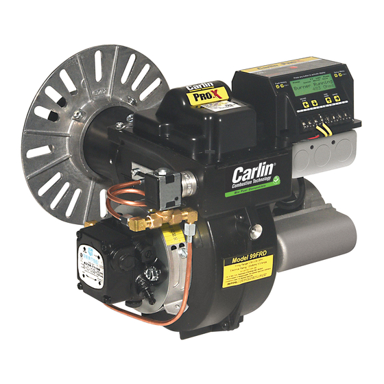
Model 99FRD, 102CRD & EZ-66 Oil Burners — Instruction Manual
2. Prepare Site • Assemble Burner • Mount Burner
Figure 1
99FRD, EZ-66 and 102CRD Minimum combustion chamber dimensions (all dimensions in inches)
L
L
L
Firing
D
T
W
rate
Target
Lined
Unlined Note 3
GPH
liner
99FRD/EZ-66
0.50
7
Line floor and
target wall or
0.65
7.5
use refractory
0.75
8
chamber
0.85
10-11
12
1.00
10
11-12
13
1.10
11
12-13
14
1.25
1.35
1.50
1.65
1.75
2.00
2.25
2.50
2.75
3.00
102CRD
14
14
17
15
15
18.5
16
16
19.5
17.5
17.5
21
18.5
18.5
22.5
20
20
24
21
21
25
25
25
29
26
26
30
27
27
31
28
28
32.5
4.00
29
29
34
4.25
30
30
35
4.50
31
31
36
– 6 –
W
DV
C
C
H
D
W
Note 5
Lined
Unlined
6
7
3
8
7
7.5
3.5
NR
9
7
8
3.5
9
7
8.5
3.5
4
9
8
9
4
4.5
10
8
9.5
4
4.5
10
with 2⁵⁄₈" air cone
15
13
6.5
6.5
15
15
13.5
6.5
6.5
15
15.5
14.0
6.5
6.5
15.5
15.5
15.5
6.5
6.5
15.5
15.5
16.5
7
7
15.5
16
17.5
7
7
16
16
18.5
7
7
16
with 3" air cone
12
23
5
5
12
13
24
5.5
5.5
13
13.5
24
6
6
13.5
14
25
6
6
14
14.5
26
7
7
14.5
15.5
27
7
7
15.5
17
28
7.5
7.5
17
F
NR
5
6
6
8
8
8
8
8.5
8.5
8.5
6.5
7
Chamber configurations
7.5
A
Chamber with water-backed floor and target wall, with refractory linings on
7.5
floor and target wall.
8.5
B
Chamber with water-backed floor and target wall, with refractory lining on
8.5
target wall only.
9
C Chamber with water-backed floor and target wall, without refractory linings.
D Refractory chamber, no water-backed surfaces (dry base design).
E
Chamber with refractory floor and water-backed target wall (without target
refractory lining).
F
Chamber with refractory floor and water-backed target wall (with target refrac-
tory lining).
Notes for dimension table
1
Some tested appliances operate well with dimensions other than shown
below.
2. Generally, applications should be acceptable with dimensions larger than
listed.
3. Horizontal cylinder chambers should have a diameter at least as larger as the
minimum width listed. For steel cylinder chambers, increase this dimension
by from 1 to 4 inches.
4. Wing walls are not recommended. Corbels can be beneficial to heat distribution
in some applications.
5. DV is the minimum diameter for vertical cylindrical chambers (refractory or
refractory-lined chambers only).
(continued)
MN99102 042015
