Carlo Loysch EBST0100R Instruções de instalação e de utilização - Página 2
Procurar online ou descarregar pdf Instruções de instalação e de utilização para Aquecedor Carlo Loysch EBST0100R. Carlo Loysch EBST0100R 4 páginas. Infrared pew radiators

2. INSTALLATION
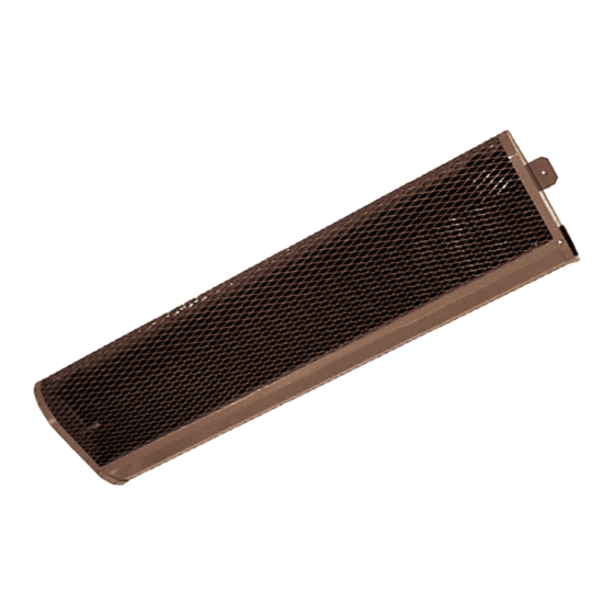
"carlo" infrared pew radiators are intended to be secured
horizontally underneath banks and church pews which are
secured into place (or weight more than 18 kg). The grate
opening must be facing the front edge of the bank. The
assembly brackets included (which ensure the necessary
spacing of 28 mm) are used for attachment to the under-
side of the bench. Two assembly brackets are provided
for each device - they are screwed to the top of the
device at the pre-punched holes with the sheet metal
screws provided.
The assembly brackets are screwed onto the underside of the bench with wooden screws (with a maximum
diameter of 4 mm and a minimum length of 20 mm; not included in the delivery). The minimum clearances
must be observed. The clearance of 28 mm between the underside of the bench and the top of the device
may not be increased with additional distances. The devices may not be installed directly underneath a wall
power socket. "carlo" infrared pew radiators have a plug and socket, and so need NOT BE OPENED UP for the
electrical connection.
The clearances MAY NOT BE SHORTER than the minimum clearances given below.
Minimum clearances:
• From the grid edge to the front edge of the seat: 50 mm
• From the rear edge of the housing to the rear edge of the seat / rear of the bench: 10 mm
• On the side between device and bench supports: 60 mm
• On the side between 2 devices: 100 mm
• To combustible materials within the grid area: 100 mm
• Between the underside of the device and the floor: 250 mm
Fixed distance between the underside of the bench and the top of the device: 28 mm This is guaranteed with
original installation brackets.
Caution: There is a risk of heat accumulation if the bench has strengthening strips on the front. The device
manufacturer must be contacted prior to installation, or air outlet slits made in the strengthening
strips.
3. ELECTRICAL CONNECTION
Only a specialist may establish the electrical connection. During installation work, conformance to applicable
regulations for installing high-voltage systems with a maximum nominal voltage of 1000 V (EN Parts 1 - 4) is a
requirement. If the heaters have a fixed connection to the power supply system, an all-phase isolator having a
3 mm contact opening as a minimum must be installed (such as an automatic cut-out or earth leakage circuit
breaker). A check must be carried out before installation on whether the mains voltage matches the operating
voltage specified on the nameplate.
All "carlo" infrared pew radiators are through-wired with 1.0 mm² heat-resistant cabling, meaning further devi-
ces (up to a maximum total nominal power of 2200 W, including the intrinsic power of devices) can be connec-
ted to a pew radiator. Every pew group is connected to 3 or 6 pews to 3/N/PE (~400V) in a star connection. All
infrared pew radiators are Protective Class I devices with nominal voltage 230 V~.
Subject to technical changes without prior notice. Typesetting and printing errors excepted.
Viewing
direction
Kirchenbankstrahler Betrieb+Montage 01/15 - 2/4
