ATI Audio DA1000 Manual de operação e manutenção - Página 4
Procurar online ou descarregar pdf Manual de operação e manutenção para Amplificador ATI Audio DA1000. ATI Audio DA1000 7 páginas. 1x8 analog audio distribution amplifier/ microamp series

light the yellow OUTPUT CLIPPING LED. Conserve power—try not to light the yellow
LED.
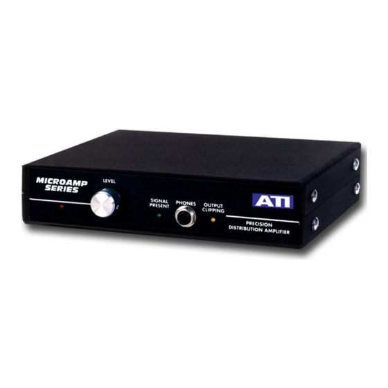
HEADPHONE OUTPUT
The front panel headphone jack provides a ninth output with its own set of build-out
resistors. The phone jack is a convenient metering point, an auxiliary output or
headphone output. The jack is wired primarily to drive stereo headphones with an in-
phase mono signal; consequently tip (red) and ring (blue) are wired together and to the HI
output, and the sleeve connection (white) is wired to the LO output. To use a standard tip-
ring-sleeve patchcord output, rewire the jack terminals by removing the blue wire from
the ring terminal, moving the white wire to the ring connection (and grounding the sleeve
terminal to the top shield foil of the P.C. board).
POWER SUPPLY
The DA1000's internal power supply incorporates a couple of unique regulating devices
called zener diodes. In contrast to most fancy IC regulators, these devices will live
through most line transients and simultaneously protect your expensive circuitry. As
further insurance, a varistor suppresser is placed across the power transformer secondary.
INSTALLATION
MOUNTING
Your DA1000 may be desk mounted on its non-slip suction cups. Rack mount system
21075-501 mounts one or two units in one rack. A 1/2RU Filler Panel, Part Number
21098-501, may be used to tidy up the installation.
WIRING
The attached line cord contains a three wire grounded plug. The third wire ground can
cause a ground loop with your facility ground. If you are sure your facility ground will
provide adequate protection to personnel in case of an AC line short to chassis, a 3-to-2
AC adapter can be used to isolate the power line ground. We recommend that the adapter
be removed and the power line ground reconnected prior to any service work requiring
removal of the facility ground from the chassis.
The four-inch silver bearing copper strap, which you are, of course, using for your
facility ground is not going to fit around the #6 chassis ground screw on the rear panel.
Run the strap to within a few inches of the chassis and jump to the chassis ground with
shield braid.
ATI Audio Inc.
■ Tel: 856-626-3480
■
Fax: 856-504-0220
■
www.
audio.com
