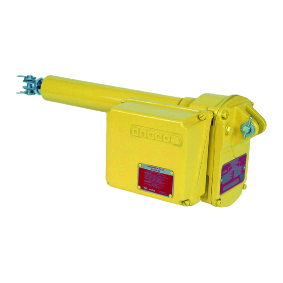
Andco Eagle Manual de instalação - Página 5
Procurar online ou descarregar pdf Manual de instalação para Controlador Andco Eagle. Andco Eagle 12 páginas.

7.1 Acceptable Lubricants
Standard lubricants and acceptable substitutions for
use in the actuator in Table 3.
Table 3 - Standard and Substitute Lubricants
Recommended
AeroShell Grease 6
Substitute
Lubriplate MAG-1
Litholene HEP1
Mobilux EP1
Gulfcrown EP1
8.0 Troubleshooting Guide
In the event of a problem with your Andco actuator,
make the following preliminary checks before
calling the factory for assistance.
1.
The actuator's rod will not extend or retract.
a. Check for a blown fuse or circuit breaker in
the wiring.
b. Check for loose wiring.
c. Check if the motor has overheated and activated
the thermal switch.
d. Check that the limit switches are set correctly.
e. Check the binding in the load being actuated.
f. Check if a capacitor lead is open.
g. Check if the drive nut is damaged or worn, by
disconnecting the actuator from the load and
pulling or pushing on the extension rod.
2.
The actuator only actuates in one direction.
a. Check that all wiring connections are secure.
b. Check that the position limit switches are
set correctly.
c. Check for an excessive external load on the
actuator in one direction.
3.
The actuator is excessively noisy.
a. Check for a damaged bearing.
b. Check for a damaged gear (chipped tooth,
missing teeth, etc.)
c. Check for a damaged screw.
4.
Actuator exhibits high motor current.
a. Check for low line voltage.
b. Check for external binding related to the load
being actuated.
c. Check for excessive external load being
actuated.
d. Check for loss of lubricant.
e. Check the extension rod for excessive
contaminates.
If you still have a specific problem with your Andco Eagle
Actuator after making all of the above checks, contact
GE for further assistance.
Manufacturer
Shell Oil Products
Manufacturer
Fiske
ARCO
Mobil
Gulf
9.0 Optional Equipment
9.1 Gear Driven Potentiometer
This optional assembly is directly driven by the operation
of the actuator and gives the capability of providing
a continuous, linear output signal directly
proportional to the actuator's stroke. The signal can be
interfaced with automatic control equipment to position
or sense the actuator at any desired stroke between
fully extended and fully retracted. The potentiometer
assembly is mounted directly to and driven by the
geared position limit switch assembly. Characteristics
of the potentiometer are 1000 ohm total resistance
±2.0% linearity, 1 watt at 40°C power rating. Input
gearing to the potentiometer is factory selected to
accommodate the full range of the actuator's strokes
and the acme screw pitches. The potentiometer has
been factory adjusted so the 0 and 1000 ohm resistance
points correspond, respectively, to the fully extended
and fully retracted rod positions. Field adjustments
may be made by loosening the jam nut holding the
potentiometer (64) to the mounting bracket (65). Rotate
potentiometer to the desired position and tighten the
jam nut. Potentiometer only to be connected to a class II
power source.
For units that utilize the last portion of the actuator
stroke only; the potentiometer gearing must be
disconnected if the unit is to be retracted beyond
the "zero" point.
5
