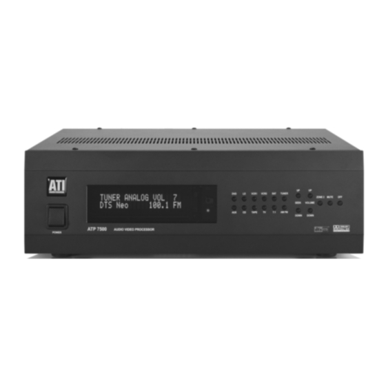
ATI Technologies ATP 7500 Manual do Proprietário - Página 7
Procurar online ou descarregar pdf Manual do Proprietário para Amplificador ATI Technologies ATP 7500. ATI Technologies ATP 7500 20 páginas. Digital preamplifier-processor
Também para ATI Technologies ATP 7500: Manual do Proprietário (20 páginas)

0. Reset to Defaults
We recommend not using this feature unless there is trouble
with any of the settings you have made. This is a quick way to
return the unit to "out of box" conditions. This will also be
used when there are updates to the firmware. Press "0" on
the remote when in the main menu. You can toggle between
"NO" and "YES" by using the SELECT button. Please exercise
extreme caution.
CAUTION: USE EXTREME CAUTION WHEN USING THIS
FEATURE AS IT COULD RETURN ALL YOUR SETTINGS TO
FACTORY DEFAULTS.
Rear Panel Connections
Audio and Video Signal Connections
The rear panel is divided into different sections whereby the
connectors are grouped together in a logical manner. Digital
inputs are grouped together and are labeled "DIG1" through
"DIG6". Each of these six digital inputs are assignable to any
of the nine labeled source inputs as previously discussed.
Most of the analog inputs with the exception of "CD", "TAPE",
and "7.1 Audio" are grouped together where they are associated
with a video input, each forming a vertical line of connectors.
For each of these labeled inputs, you can plug in one video
input, allowing for a choice of the type of connection: either a
choice of Composite Video and S-Video or Component Video
and S-Video. The "7.1 Audio Input" is a special multi-channel
analog pass-through that can be used for a DVD-Audio or
SACD player.
The outputs are grouped into "MAIN OUT" and "RECORD
OUT" sections. The "MAIN OUT" section has an eight channel
(7.1) preamplifier output and 4 video outputs; two are
Composite Video and one is S-Video and one is Component
Video. ONLY the Composite and S-Video outputs carry the
OSD signal. To correctly setup your ATP7500 using the
previously discussed OSD menus, make sure to connect your
screen to at least one of the Composite or S-Video outputs
All manuals and user guides at all-guides.com
and remember to select this input on your screen whenever
you need to access the OSD of the ATP7500.
The "RECORD OUT" section has two audio/video outputs that
you can use to connect to a VCR or a tape deck, for example.
The audio outputs are fixed line level; they are not affected
by the processor's volume control setting. The video outputs
are Composite Video and S-Video for each of the two "RECORD
OUT" connections. These video outputs provide NO OSD
information. There is also a digital output available on an
optical TOSLINK connector located near the "DIGITAL INPUTS".
It may be used to connect to a CD-R recorder for example.
The "2nd Zone" section has one fixed output, one variable
output and one second zone dedicated input that is accessible
only from the "2nd Zone". The "2nd Zone" has limited access
to which input source may be selected; the dedicated "2nd
Zone" input, CD, TAPE, or the AM/FM Tuner.
Control Signal Connections
The input labeled "IR INPUT" (infrared remote control) is
designed to receive an electrical signal corresponding to the
infrared signal of a remote device such as a repeater that may
be installed in the "2nd Zone".
The RS232 port allows the control of the ATP7500 from a
distant programmed controller (such as a Crestron
Information about the RS232 codes can be obtained from
ATI on request. The RS232 port can also be used to download
software revisions for future upgrades.
There are three trigger outputs that can be used to control
other components. Two are associated with the main zone
and one with the "2nd Zone". Each of them activates when
their respective zone is turned on. The output labeled "12V
Trigger" is rated at 200mA. The outputs labeled "2nd Zone
Trigger" and "Main Zone" are dry contacts rated at 1A each.
All triggers operate with a 5 second delay.
system).
®
Page 7
