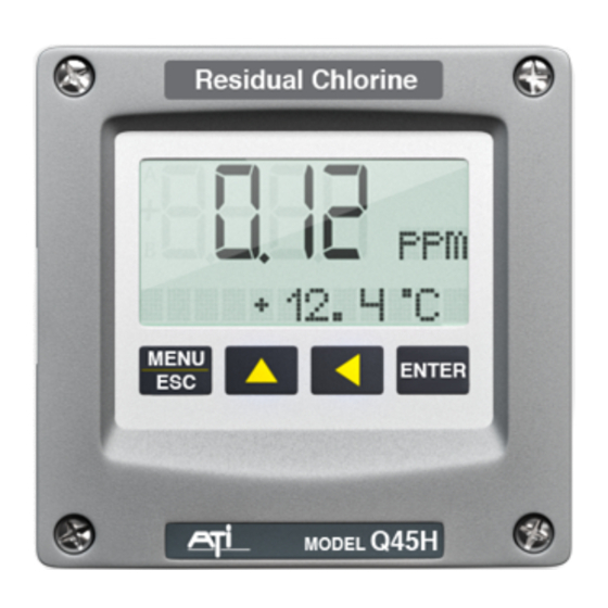
ATI Technologies Q45H/62 Manual - Página 10
Procurar online ou descarregar pdf Manual para Instrumentos de medição ATI Technologies Q45H/62. ATI Technologies Q45H/62 11 páginas. Free chlorine measurement system

Analytical Technology Unit 1 & 2 Gatehead business PK, OL3 5DE
Phone +44 145 783 2800
Fax +44 145 783 9500
Quick Reference Guide (PRINT OFF AND DISPLAY)
Observation Checklist
1. Flow through the cell going over weir.
2. Check the pH reading is the same and correct.
3. Try to calibrate span (REF 1)
Scroll to the CAL menu section and press ENTER. Cal Cl2 will be displayed.
•
Press the ENTER key. The screen will display a flashing 1-Ref for span calibration.
•
Press the ENTER key. Waiting will be displayed.
•
Take a hand held chlorine measurement and the last ppm measurement will be display. Using
•
the arrow keys to adjust to the new reading.
Press the ENTER key. If accepted the display the message PASS.
•
The sensor offset value is display in % from the last calibration
•
If the calibration fails, a message indicating the cause of the failure and the FAIL icon will be
turned on.
4. If this is accepted the unit just needed to be calibrated.
5. If this is not accepted.
6. Note the sensitivity of the sensor.
7. The range of acceptable values for slope is 20-500% (if the sensitivity<12%). It will be necessary to
rebuild sensor.
8. Inspect the sensor end is it white or dirty.
Rebuilding Sensor
1. Unscrew the electrolyte chamber from the assembled sensor and also remove the fill screw from the
side of the sensor body.
2. Remove the front nut from the bottom of the chamber and discard the protective membrane. O-
rings are contained in grooves on both the bottom and top of the chamber. Be sure that these o-
rings remain in place.
3. From the package of membranes supplied with the sensor, place a new membrane into the front nut.
The membrane is white in colour and is separated from other membranes by a light blue paper
spacer.
4. Screw the front nut on to the chamber until you feel the o-ring compress. Hand tight compression is
all that is needed. Do not use tools to tighten. The membrane should be flat across the bottom of
the chamber without wrinkles.
5. Fill the chamber with electrolyte until the level reaches the bottom of the internal threads.
6. Slowly screw the chamber onto the sensor body. A small amount of electrolyte will run out of the
hole from which the fill screw was removed. Place a paper towel around the sensor to absorb the
electrolyte overflow. The electrolyte is harmless and will not irritate skin. Tighten the chamber until
the o-ring at the top of the chamber is compressed. Once again, do not use tools to tighten.
7. Shake excess electrolyte from the fill hole on the side of the sensor and replace the fill screw.
CAUTION:
impacts on the tip of the sensor from dropping or other misuse may cause permanent damage to the sensor.
Q45H Training Handout 4.05
When handling the assembled sensor, do not set the sensor on its tip or damage to the membrane will result. Severe
Page 9 of 11
.
