ATI Technologies BQ2208 Manual de instruções - Página 4
Procurar online ou descarregar pdf Manual de instruções para Aquecedor de água ATI Technologies BQ2208. ATI Technologies BQ2208 8 páginas. Marine water heater with dual heating

INSTALLATION
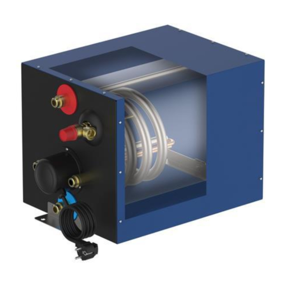
Main parts (see FIG_5-3):
1. Storage tank: it is entirely made of steel submitted internally to a double enamelling treatment that is a vitreous
coating cooked at over 850 °C;
2. External coating in aluminum: it is highly resistant to shocks and external solicitations, having at the same time a very
pleasant design;
3. Thermal insulation: made of expanded polyurethane with closed cells avoids unnecessary heat losses. In this way
the heat loss by thermal inertia is reduced to 1 ° C per hour for a period of 24 hours;
4. Heat exchanger (only models BQ22XX): it is made of enamelled iron and its exchange surface allows to exploit at
best the heat of the engine cooling water and to get hot water also in extreme conditions (very small temperature
differences);
5. Electrical resistance: the device is equipped with an electric heating element to heat the water even when the boat
engine is turned off (for example when the boat is on the dock). Material: Incoloy corrosion resistant alloy.
6. Thermostat: has two functions, namely:
a. Temperature control: it interrupts the power supply to the heater element when reaching the set temperature
b. Overtemperature safety: it interrupts the power supply to the resistance in case of excessive water
temperature.
Thermostat characteristics:
temperature 83 ° C; maximum current 16 A;
7. Cold water inlet;
8. Heat exchanger connection (only model BQ22XX);
9. Hot water outlet;
10. Safety of combined temperature and pressure relief valve protects the tank from possible excessive pressures
caused by the expansion of water during heating. Automatically, without the assistance of different energy from that
of the hot fluid under pressure, discharge a quantity of fluid such as to prevent them from being exceeded the
predetermined pressure and temperature limits to protect the storage tanks. Calibration: 700 kpa / 99 ° C;
11. Mounting brackets;
12. Magnesium sacrificial anode: prevents corrosion of the tank;
13. Power supply cable with schuko plug.
6. GENERAL WARNINGS
The installation must be performed in accordance with current legislation, by a qualified person who can do, not only
a proper set up of the device, but also the necessary tests before starting the water heater.
During the original installation and subsequent maintenance, follow the instructions in this booklet carefully. Changes
to any type of connection or failure to follow instructions will cause the warranty expires.
Before the installation, maintenance or repair, remove the power supply unit.
WARNING: USE THE BOILER ONLY FOR APPLICATIONS IN THIS SECTION. DO NOT USE THIS
EQUIPMENT FOR OTHER TYPES OF OPERATION. THE BUILDER IT ASSUMES NO RESPONSIBILITY
FOR INCIDENTAL OR CONSEQUENTIAL DAMAGES CAUSED BY IMPROPER APPLIANCE.
7. POSITION AND ASSEMBLY
The appliance is equipped with two fixing brackets (A - FIG_7-1). In this way we get an easy, but fixed and stable installation.
The device must be installed horizontal or in such a way that the heat exchanger and / or the electrical resistance are placed
in the lower part (FIG_7-2).
The unit can be installed in any room, without any restrictions. The above does not exempt from complying with the
instructions provided in the section "General precautions" at the beginning of this booklet.
For other installation not covered in this manual and for installation on sloped walls contact our technical department.
8. HYDRAULIC CONNECTIONS
To extend the life of the appliance water quality must meet the following parameters:
1.
hardness comprised between 15 and 50 ° F (in
particular, where the water has undergone a softening
or desalination treatment)
Minimum pressure water inlet: 70 kpa.
Maximum water inlet pressure: 750 kpa (for higher inlet pressures is necessary to mount a pressure reducer with
compensation of inlet pressure; adjustable downstream pressure, max 700 kpa)
Connect the appliance according to the following directions:
Connections (FIG_8-1):
1. cold water inlet
2. hot water outlet
3. Water supply to the engine cooling circuit
4. return water from the engine cooling circuit
temperature control 0-60 °C;
2.
3.
4.
1/2 "
1/2 "
1/2 "
1/2 "
differential temperature about 9 ° C; intervention
chlorides comprised between 25 and 100 mg / l
PH between 6.5 and 9.5
conductivity between 400 and 1500mS / cm
Plant scheme (FIG_8-2):
A. sanitary water tank
B. pump
C. pressure reducer
D. non-return valve
E. water heater
F. engine cooling circuit
ENGLISH
210-0338 – edizione 2018-11
