COMMUNICATIONS-APPLIED TECHNOLOGY AMCVIS Manual de instruções - Página 4
Procurar online ou descarregar pdf Manual de instruções para Sistema de intercomunicação COMMUNICATIONS-APPLIED TECHNOLOGY AMCVIS. COMMUNICATIONS-APPLIED TECHNOLOGY AMCVIS 16 páginas. Advanced multi-channel vehicle intercom system (amcvis) with digital crew control

THEORY OF OPERATION
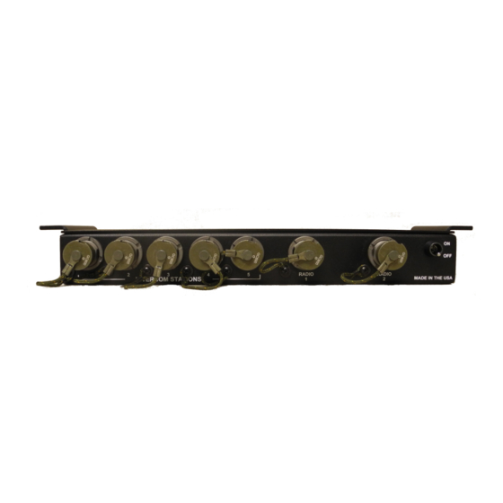
The AMCVIS-D (p/n 500.7045) provides up to five personnel with a two way intercom capability.
All headset station ports have common capabilities.
The AMCVIS-D provides the five users with the ability to simultaneously monitor two, 2-way
radios---connected to the AMCVIS---and to transmit on one of them. Selection of the Radio to be
transmitted on is made at a switch located on the individual users ICU. When a radio is selected for
both monitoring and transmitting, the other radio is automatically monitor only.
All users hear all voice transmissions by the other users whether the Intercom or a Radio is keyed at
an ICU.
A user hears his own voice in his headset when he is keying either the intercom or the radios from
his ICU.
This "sidetone" circuit provides the user with confirmation that all parts of his
communications system is operating properly.
Each ICU is configured with two volume controls. These rotary controls permit the user to adjust
the listening level in his own headset from a preset minimum to maximum volume (approximately
0.5 watt into 50 ohm speaker). Adjusting the level on one's ICU does not affect the listening level of
the other users. One volume setting independently controls the radio that the user currently has
selected to transmit/receive. The other volume control is a master control to each users' overall
system volume.
Each user is configured with a radio selector switch to independently select which radio will be used
in "monitor only" and which radio will be used to transmit and receive.
Separate, momentary, push-to-talk switches are provided for the intercom and radio "keying"
functions. These are located on the individual ICUs and protected by guards. Keying a radio also
places the user's voice in the intercom for other users to monitor.
Variety of headsets can be used with the intercom system. The system accommodates most types of
dynamic and 2-wire electret type microphones and headset speaker impedances from 50 to 2000
ohms.
The Intercom Master Unit (IMU) and Intercom Control Unit (ICU) are designed to comply with
military environmental shock and vibration specifications.
A limiter and speech frequency filter circuits in each channel control the level of the headset
microphone and filter out extraneous noise.
To reduce potential acoustic feedback between the headset speakers and the headset microphone, the
side tone is attenuated by as much as 32dB (adjustable from inside of the master intercom unit).
Power requirement for this intercom system is +11 to +24 volts DC from an external power source.
The power input is protected by a self-resetting fuse, which can be quickly reset in the field without
tools. Current requirements are 350mA at 11V during initial "start up" and normally at 300mA.
- 3 -
