Dresser Texsteam TA 0179 Manual de instalação e operação - Página 2
Procurar online ou descarregar pdf Manual de instalação e operação para Controlador Dresser Texsteam TA 0179. Dresser Texsteam TA 0179 8 páginas. Multipoint injection controller
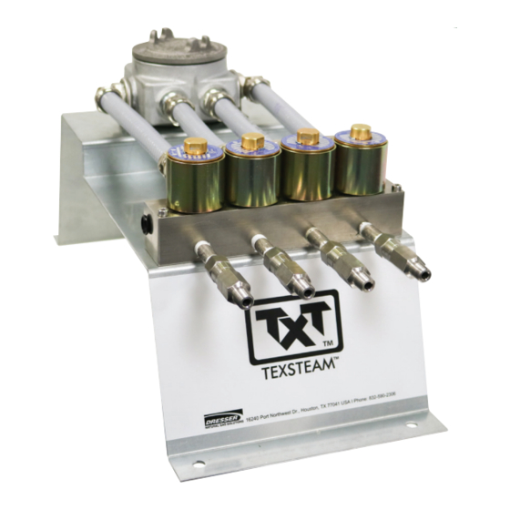
Serialized Assemblies
It is strongly advisable that all assemblies remain complete
or unbroken serialized set for proper functionality. These
assemblies have been adequately sized based on the
following variables: daily volume, head size, well pressures,
regional sun hours, temperature, number of days without
sun light, and quantities of batteries and solar panels.
WARNING
Minimum personal protection equipment (PPE) required
for installation & maintenance of this unit: safety goggles,
glove, steel toe shoes, hardhat, fire retardant suit.
WARNING
This equipment is designed to operate at temperatures
between -40° F to 140° F. Prior to going on-site for installation
or maintenance, make sure proper safety equipment is worn
before handling the equipment and that you are properly
dressed for the work site environment temperatures.
Pump Motor Controller Connection
Connect cable conduit from multipoint junction box to
controller box. Run cable connectors through installed fitting
in the box, and tight conduit fitting. Connect solenoids to
cable matching connector coming from I/O Relays. Also
connect ground, or black cable.
2
™
Multipoint Configuration
On ICIP Controller click down, until setup, left to setup
options, and down until solenoids. Enable each solenoid
by entering the % percentage desired. Refer to menu tree
(figure below). To disable a solenoid % must be set to 0%.
NOTE: All solenoids % must add to 100%, OTHERWISE PUMP
WILL NOT START.
iCIP Controller Menu Tree - Basic
Faults
F a u lts
Displays current faults
Operation
Stop
O pera tio n
S to p
Stop the pump motor
Run
R u n
Start the pump motor
Run Schedule
R u n S c h edu le
Run a schedule
Daily Volume
Setup
n.nn
S etu p
D a ily V o lu m e
n.nn
Units
US
U nits
U S
s1
S I
Main Head Size
M a in H ea d S iz e
Startup
Stop
S ta rt U p
S to p
Run
R u n
Run Schedule
R u n S c h edu le
Clock
Minutes
C lo c k
M inu tes
Hours
H o u rs
Day
D a y
Month
M o nth
Year
Y ea r
1
No. of Main Heads
1
N o . o f Ma in H e a ds
2
2
3
3
2nd Head Size
2nd H ea d S iz e
3rd Head Size
None
3rd H ea d S iz e
N o ne
3/16
3/1 6
1/4
1 /4
3/8
3/8
1/2
1 /2
Solenoids Activation
Enable Solenoid 1
S o le n o ids A c tiva tio n
E na ble S o leno id 1
E na ble S o leno id 2
Enable Solenoid 2
Enable Solenoid 3
E na ble S o leno id 3
Enable Solenoid 4
E na ble S o leno id 4
For % solenoid adjustment and flow rate refer to table
SP2217, or (SP2218 for 65 RPM Motor) located on ICIP
Controller Box, and next page.
Volume required - head size dependant
Quarts
Liters
3/16
3/1 6
1/4
Selecte option,
1 /4
will initiate once
3/8
power suppled
3/8
to controller
1/2
1 /2
0-59
0 - 59
Set the minutes
0-23
0 - 23
Set the hour
0-31
0 - 31
Set the day
1-12
1 - 1 2
Set the month
2000-2078
2000 - 2078
Set the year
Select 1 if single head unit or multiple head unit and
wish to display head volumes independently. Primary head: 1
Select 2 if dual head unit and adding up the
volumes of both heads. Primary heads: 2
Select 3 if triple head unit and adding up the
volumes of all three heads. Primary heads: 3
2000-2078
N o ne
3/16
3/1 6
Select appropriate heads size
1/4
1 /4
Select "none" if no head present
3/8
3/8
1/2
1 /2
X%
Enable
x %
0%
Disable
0%
X%
Enable
x %
0%
Disable
0%
X%
Enable
x %
0%
Disable
0%
X%
Enable
x %
0%
Disable
0%