Dresser Masoneilan 10000 Series Manual de instruções - Página 7
Procurar online ou descarregar pdf Manual de instruções para Unidade de controlo Dresser Masoneilan 10000 Series. Dresser Masoneilan 10000 Series 12 páginas. Double ported globe valves
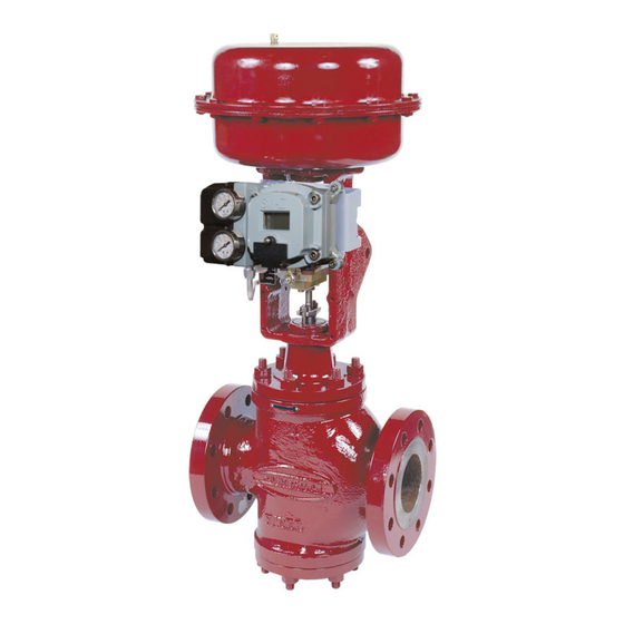
Figure 7
C. Cut off the stem directly above the pin hole. (see figure 6).
D. rethread the stem the original amount.
Note: The area of the plug stem marked X in Figure 8,
serves as a guide and must be checked to ensure a close
fit in the valve plug.
Stem
Hole
Dia.
Dia. "A"
Inches
in
mm
½
0,188
4,78
0,219
5,56
5
/
8
0,250
6,35
¾
1
0,312
7,92
Figure 8
E. screw the stem solidly into the plug.
Note: This can be checked by measuring the depth of
the pilot recess in the plug (X in Figure 8), and making a
reference mark on the stem the same distance from the
thread. When properly assembled, the reference mark
should be flush with the end of the guide section.
F. Place the plug guide on a v block and using a suitable size
drill, drill the stem using the hole in the plug as a guide.
G. remove any burrs from the plug guide by making a slight
counter bore.
H. select the correct size pin, apply a small amount of grease
on it and press into the hole.
Note: The pin must be recessed approximately 1/16" below
the plug guide surface.
I. After the plug has been pinned it should be placed in a lathe
to ensure it is running true. If it is not, strike the plug with a
soft faced mallot to straighten.
Note: The plug should be placed in a collet with the plug
guide against it and the plug should be struck.
Instructions eh10000 - 06/10
10000 series Double Ported globe valves
"B"
"X"
in
mm
in
1,250
31,75
0,50
12,7
1,562
39,67
0,62
15,7
1,875
47,63
0,75
19,1
2,500
63,50
1,00
25,4
6.5 Packing Box
Packing box maintenance is one of the principle chores of
routine servicing. Tightness of the packing is maintained by
packing compression. Compression is achieved by evenly
tightening the packing flanged nuts (2) against the packing
flange (3). Care must be taken not to over tighten, as this could
prevent smooth operations of the valve. If all compression is
used up and the valve leaks, new packing is required.
valve must be isolated and pressure vented before performing
packing box maintenance.
Proceed as follows:
A. loosen and remove packing flange nuts (2).
B. raise packing flange (3) and packing follower (19) up the
valve stem.
C. remove packing (17).
Note: Only the top pieces of the old packing are removable
by pulling them out the top of the bonnet. To remove all the
packing the bonnet must be removed. (See appropriate
section)
D. replace packing. As a rule, 2/3 of the packing rings are
placed below the packing spacer, and 1/3 above.
Note: Ensure packing is inserted with skives 90˚ apart on
successive rings.
E. replace packing follower (19) and packing flange (3).
mm
F. replace and tighten packing flange nuts (2).
Do not over tighten.
G. Put valve back in service and tighten packing only as much
as is necessary to stop leaking.
Note: In an emergency, string packing may be used as a
temporary repair only and must be replaced with the correct
packing as soon as possible.
6.6 Packing Box (Optional Lubrication Figure 7)
In some applications, packing boxes are designed for use with
a lubricator. The lubricator is provided with a ball check valve
to present backflow of the process fluid. on some valves, an
isolating valve (67) is added for positive protection against
backflow. The lubricator (66) should be kept filled with the
specified lubricant and turned in firmly but not tightly. one or
two turns of the lubricator once every two weeks should suffice
to provide the desired seal. lubricants are available through
your Masoneilan representative or District office. replacement
of the packing (17) is accomplished in the same manner as the
standard lubricator box. Care must be taken to ensure that the
latern ring (18) is in line with the lube hole located in the bonnet.
As a rule, 2/3 of the packing rings are inserted below the lantern
ring and 1/3 above.
5