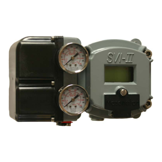
Dresser Masoneilan SVI II AP Manual de início rápido - Página 12
Procurar online ou descarregar pdf Manual de início rápido para Equipamento de gravação Dresser Masoneilan SVI II AP. Dresser Masoneilan SVI II AP 20 páginas. Smart valve interface with remote position sensor

I I n n s s t t a a l l l l a a t t i i o o n n a a n n d d S S e e t t U U p p
Installation Procedure
Installation Procedure
T T able
able 2 2 Remote
A A c c t t u u a a t t o o r r S S i i z z e e
6 6 a a n n d d 1 1 0 0
1 1 0 0
Comply with current national and local regulations
Comply with current national and local regulations
for electrical installation work.
for electrical installation work.
Comply with national and local explosive
Comply with national and local explosive
atmosphere regulations.
atmosphere regulations.
Before carrying out any work on
Before carrying out any work on the device, power
off the instrument or make sure that the locale
off the instrument or make sure that the locale
conditions for potentially explosive atmosphere
conditions for potentially explosive atmosphere
permit the safe opening
permit the safe opening of the cover.
For the Remote Position Sensor installation procedure refer to the
For the Remote Position Sensor installation procedure refer to the
mounting instructions provided with the Remote Position Sensor
mounting instructions provided with the
1. 1.
Remove the cover from the Remote Position Sensor
Remove the cover from the Remote Position Sensor
assembly by turning the cover in a counter-clockwise (fac-
assembly by turning the cover in a counter-clockwise (fac-
ing the cover) direction.
ing the cover) direction.
2. 2.
Connect the Remote Position Sensor to the mounting
Connect the Remote Position Sensor to the mounting
bracket by inserting four M6 x
bracket by inserting four M6 x 20 mm Socket Head Cap
Screws through the appropriate screws holes (according
Screws through the appropriate screws holes (according
to the valve) on the Remote Position Sensor brack
to the valve) on the Remote Position Sensor bracket and
using a 3 ⁄ ⁄ 1 6 inch Hex Key with tee handle.
using a 3
3. 3.
Route the instrument cable from the SVI II AP to the
Route the instrument cable from the SVI II AP to the
Remote Position Sensor (see
Remote Position Sensor (see Figure 3 on page 6
installation instructions).
installation instructions).
4. 4.
Thread the cable through the conduit at the
Thread the cable through the conduit at the bottom of the
Remote Position
Remote Position Sensor
5. 5.
Using a blade screwdriver, loosen the screws on the
Using a blade screwdriver, loosen the screws on the
terminal block and connect the black, brown and red wires
terminal block and connect the black, brown and red wires
to the appropriate labelled connectors.
to the appropriate labelled connectors.
6. 6.
Tighten the screws.
Tighten the screws.
7. 7.
Attach the feedback lever to the Remote Position Sensor
Attach the feedback lever to the Remote Position Sensor
shaft.
shaft. From the cover side,
From the cover side, the lever should be poi
the left for reciprocating valves and to the right
the left for reciprocating valves and to the right for rotary
valves.
valves.
8. 8.
Place the Remote Position Sensor on the mounting
Place the Remote Position Sensor on the mounting
bracket.
bracket.
9. 9.
Attach the Remote Position Sensor and secure the
Attach the Remote Position Sensor and secure the
turnbuckle to the lever ensuring that the shaft at the rear of
turnbuckle to the lever ensuring that the shaft at the rear of
the Remote Position Sensor is inserted into the valve
the Remote Position Sensor is inserted into the valve
actuator. (Refer
actuator.
Turnbuckle Length"
Turnbuckle Length" below for turnbuckle length.)
10.
10.
Replace the Remote Position Sensor
Replace the Remote Position Sensor cover.
Remote Position
Position Sensor
S S t t r r o o k k e e
0 0 . . 5 5 - - 0 0 . . 8 8 i i n n c c h h
0 0 . . 5 5 - - 0 0 . . 8 8 i i n n c c h h
I I n n s s t t a a l l l l i i n n g g t t h h e e S S V V I I I I I I A A P P R R e e m m o o t t e e P P o o s s i i t t i i o o n n S S e e n n s s o o r r
Remote Position Sensor. .
16 inch Hex Key with tee handle.
Sensor. .
the lever should be pointing to
(Refer to to Table 2 "Remote Position Sensor
Table 2 "Remote Position Sensor
below for turnbuckle length.)
Sensor T T urnbuckle Length
urnbuckle Length
T T u u r r n n b b u u c c k k l l e e L L e e n n g g t t h h
5 5
the device, power
of the cover.
20 mm Socket Head Cap
Figure 3 on page 6 for
bottom of the
for rotary
cover.
1 1 . . 2 2 5 5 i i n n c c h h
1 1 . . 2 2 5 5 i i n n c c h h
et and
for
nting to
