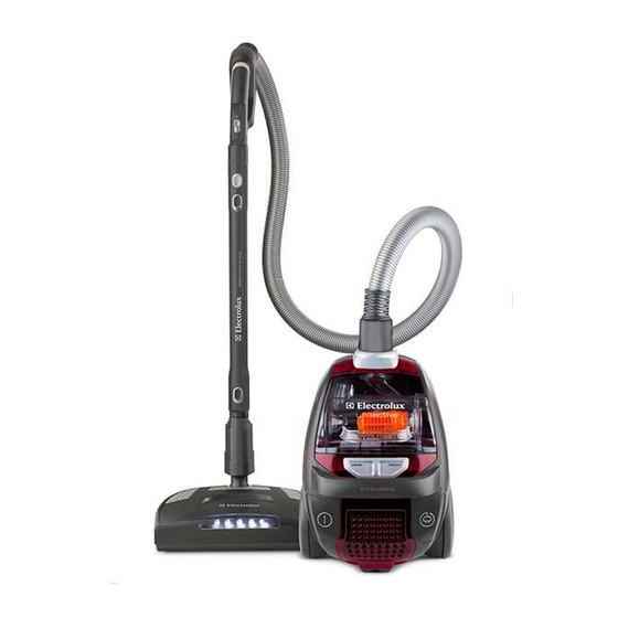
Electrolux EL4300 Manual de serviço - Página 2
Procurar online ou descarregar pdf Manual de serviço para Aspirador de pó Electrolux EL4300. Electrolux EL4300 37 páginas.

TABLE OF CONTENTS
1
General description .................................................................................................................................... 3
1.1
Exploded view....................................................................................................................................... 5
2
ACCESSIBILITY......................................................................................................................................... 7
3
Levels of Electronic Control...................................................................................................................... 22
3.1
Display Layout for models without remote controlled HBTN:............................................................. 22
3.1.1Basic software functionality ........................................................................................................... 22
3.1.2 Motor power regulation and LED-functionality ................................................................................... 22
3.2
Display Layout for models for passiver remote system:..................................................................... 25
3.2.1 Basic software functionality ................................................................................................................ 25
3.2.2 Motor power regulation and LED-functionality ................................................................................... 25
3.3
Display Layout for models with Aeropro active system: ..................................................................... 23
3.3.1 Basic Software functionality................................................................................................................ 23
3.3.2 Motor power regulation and LED-functionality ................................................................................. 236
3.3.3 Brush motor functionality .................................................................................................................... 24
3.4
Nozzle power supply interface............................................................................................................ 26
3.5
Brush nozzle PCB 230V/110V active remote..................................................................................... 26
3.6
Standby indication (for both RF and active versions)......................................................................... 26
3.7
Reprogramming RF remote controller.................................................................................................28
3.8
PCB's .................................................................................................................................................. 27
3.8.1
3.9
..................................................................................................................................... 30
3.10 Pressure switch PCB..........................................................................................................................31
4
PCB Power Module (position 014A)....................................................................................................... 302
4.1
Introduction ......................................................................................................................................... 32
4.2
Connection for control unit.................................................................................................................. 32
4.3
Low Current Power Module ................................................................................................................ 33
4.3.1 Power supply design low current power module ................................................................................ 33
4.3.2 Electrical specification ........................................................................................................................ 33
4.4
High Current Power Module ............................................................................................................... 33
4.4.1 Electrical specification switched power supply................................................................................... 33
5
RF transmitter........................................................................................................................................... 34
5.1
Introduction ......................................................................................................................................... 34
5.2
Design................................................................................................................................................. 34
5.2.1 Mechanical design, PCB shape.......................................................................................................... 34
5.3
LED indication..................................................................................................................................... 34
5.4
Changing the battery .......................................................................................................................... 34
6
Aeropro PCB 230V/110V motor ............................................................................................................... 35
6.1
Introduction ......................................................................................................................................... 35
6.2
PCB variants....................................................................................................................................... 35
6.3
Electrical overview .............................................................................................................................. 35
6.3.1 Functional description......................................................................................................................... 36
6.4
Description Remote control signal and handling ................................................................................ 36
6.5
Motor output........................................................................................................................................ 36
7
INDICATION & DIAGNOSTICS ............................................................................................................... 37
7.1
Filter and S-bag indicators.................................................................................................................. 37
7.1.1 Activation ............................................................................................................................................ 37
7.1.2 Deactivation ........................................................................................................................................ 37
7.2
Error indication.................................................................................................................................... 37
7.2.1 Level 1 potentiometer is not connected.............................................................................................. 37
7.2.2 Level 2-3, error indication and function .............................................................................................. 37
7.2.2.2 Error (low prio)..................................................................................................................................37
7.2.2.3 Error summary..................................................................................................................................38
8
TROUBLE SHOOTING ............................................................................................................................ 39
EN
Publication number
.......................................................................................................... 29
......................................................................................................................
Nr
Rev. xx
Month/year
2
37
PR - 2/37
