Drill Master 95578 Manual de instruções de instalação e funcionamento - Página 13
Procurar online ou descarregar pdf Manual de instruções de instalação e funcionamento para Moedor Drill Master 95578. Drill Master 95578 20 páginas. 4-1/2” angle grinder
Também para Drill Master 95578: Manual de instruções de montagem e funcionamento (16 páginas)
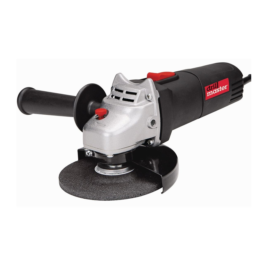
Functions
Switch
Side Handle
Spindle
Lock
Wheel
Guard
Bolt
Switch - Press the Switch forward to
turn the tool on; pull it backward to
turn the tool off.
OPERATING INSTRUCTIONS
Read the ENTIRE IMPORTANT
SAFETY INFORMATION
section at the beginning of this
manual including all text under
subheadings therein before set
up or use of this product.
Tool Set Up
FROM ACCIDENTAL
OPERATION:
Turn the Power Switch of the
tool off and unplug the tool
from its electrical outlet
before installing accessories.
Installing a Non-threaded Grinding
Wheel
1.
The Grinding Wheel MUST be:
• rated to at least 11,000 RPM.
• no larger than 4-1/2" in diameter.
• fitted with a 7/8" round arbor hole.
• from 0.08" to 1/4" thick.
SKU 95578
Wheel
Guard
TO PREVENT
SERIOUS INJURY
For technical questions, please call 1-800-444-3353.
• a type of grinding wheel suitable for
surface grinding, not edge grinding.
• dry and clean.
• proven undamaged by inspection
and by the ring-test explained
below.
2.
Press in and hold the Spindle Lock
Button to prevent the Spindle from
turning.
3.
Use the Pin Wrench to remove the
Outer Flange. Keep the Inner Flange
in position on the Spindle.
4.
Closely inspect the Grinding Wheel
before mounting. Perform a ring-test
on the wheel (unless wheel is smaller
than 4" or is an unusual shape) as
follows:
a. Suspend wheel using a pin or finger
through the arbor hole.
Hang
Wheel
from
Pin
Tap
Wheel
Here
b.
Tap the flat side of the wheel with a
light non-metallic object, such as a
screwdriver handle, at a point 45°
from the vertical center line on each
side of the wheel and 1 – 2 inches
from the edge of the wheel (see
Illustration).
45°
45°
V
E
R
T
I
C
A
L
C
E
N
T
E
R
45°
45°
REV 10c; 11a
Page 13