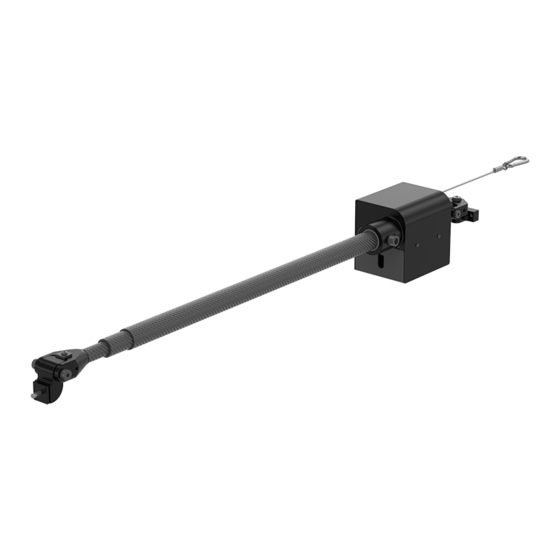
Atlas Copco SMC 100 2100 POSI 3 Instruções do produto - Página 6
Procurar online ou descarregar pdf Instruções do produto para Ferramentas Atlas Copco SMC 100 2100 POSI 3. Atlas Copco SMC 100 2100 POSI 3 12 páginas. Torque arm

Installation
Installation
Installation instructions
Installing the SMC torque arms in trolley and rail systems
Do not modify the torque arm or the torque arm attachment. The installed torque arm must be able to
swivel in all directions.
Installing the torque arm
The tool torque should not exceed the specified torque range of each specific arm.
The angle of tool holder attachment, ω, is limited to 0° at SMC Posi 3 to achieve proper accuracy for
positioning.
Mounting on a ceiling
■
Put the mounting point straight above, or as close as possible to, the point where the torque is ap-
plied.
■
Make sure that the fixation point can handle the weight and the torque of the chosen torque arm.
■
Attach the safety wire (see Spare Parts) to a second point that does not limit the working area.
Attaching and balancing the tool when mounted on the ceiling
1.
Mount the arm straight above, or as close as possible to the work area.
2.
Attach the tool holder to the tool.
3.
Attach the tool holder to the arm.
■
SMC 12/25 (M6) - 10 Nm
■
SMC 50/100 (M8) - 24 Nm
4.
Install the set screw on the tool holder and tighten it to 2.5 Nm.
5.
Attach a balancer to the torque arm by using Atlas Copco balancer adapter kit and hook it up with the
tool.
6.
Adjust the balancer to carry the weight of the torque arm, the tool holder and the tool.
7.
Adjust the wire stop of the balancer so that the torque arm cannot be fully retracted.
8.
Secure all the screws with the set screws (see Spare Parts) and tighten them to 2.5 Nm.
6
EN
© Atlas Copco Industrial Technique AB - 9839 1431 01
SMC 100 2100 POSI 3
