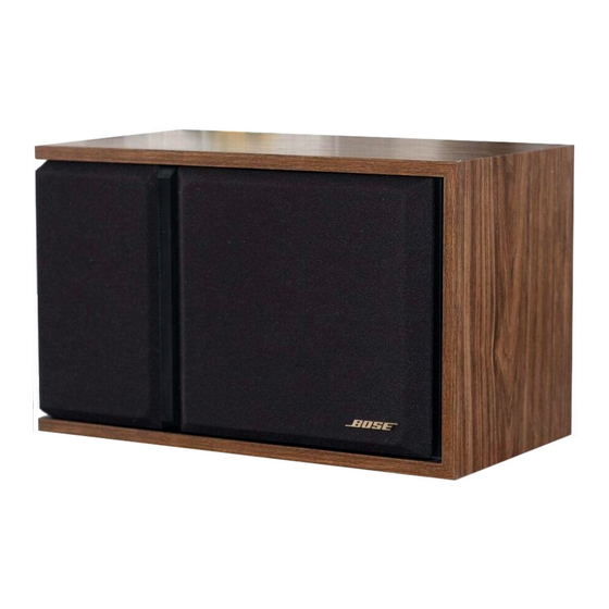
Bose 301 Series III Manual de serviço - Página 4
Procurar online ou descarregar pdf Manual de serviço para Sistema de altifalantes Bose 301 Series III. Bose 301 Series III 13 páginas. Direct/reflecting
Também para Bose 301 Series III: Manual do Proprietário (10 páginas)

Schematic Diagram
FIGURE 2
5. Woofer Phase Test
NOTE: Supply voltage should only be momentarily applied to the speaker input terminals to
avoid possible damage to the speaker.
A. Set a DC power supply to 8 volts. To ensure that the woofer is connected in phase,
connect the positive lead of the supply to the positive (+) speaker input terminal and the
negative lead to the negative (-) input terminal. The woofer should move outwards with the
application of the supply voltage.This ensures that the woofer and speaker input terminals
are wired in phase. See Schematic Diagram, Figure 2.
6. Tweeter Phase Test
A. Remove 4 screws and lift the woofer carefully away from the speaker cabinet in order to
access the terminal cup. Check the wiring on the terminal cup and on both sets of tweeter
terminals against the schematic in Figure 2. This ensures that both tweeters are wired in
phase.
REMOVING THE GRILLE ASSEMBLY
A. The grille assembly is held in place by 6 grille fasteners. To remove, CAREFULLY pull
the assembly away from the speaker (it should lift away easily).
REPAIR PROCEDURES
1. Replacing the Woofer
A. Remove the 4 screws holding the woofer in place. (Refer to Figure 3 for an exploded
view of the speaker assembly). Lift the woofer out and cut the wires connected to the
woofer terminals as close to the terminals as possible. Strip the wires and connect to the
replacement woofer. Make sure that the yellow wire is connected to the positive (+) terminal
and the green wire is connected to the negative (-) terminal of the woofer. Remount the
woofer to the cabinet using the 4 screws. Repeat the woofer test procedure.
3
