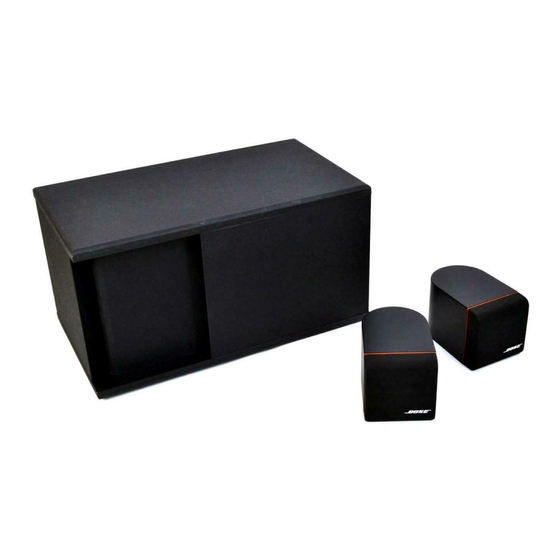
Bose Acoustimass 3 Series Manual de serviço - Página 9
Procurar online ou descarregar pdf Manual de serviço para Sistema de altifalantes Bose Acoustimass 3 Series. Bose Acoustimass 3 Series 42 páginas. Powered speaker system
Também para Bose Acoustimass 3 Series: Manual do Proprietário (17 páginas), Manual do Proprietário (10 páginas), Manual (43 páginas)

nd
The U103 stage is a combination 2
order 200 Hz high-pass filter and 5 dB 2 kHz dip (notch)
filter. The U104 stage provides the 5 dB peak at 200 Hz and the sharp band-reject between
100 and 200 Hz. Finally, the U105 stage is a combination 2
nd
order 20 kHz low-pass filter and
2 dB 350 Hz notch filter.
5. Bass Control
The bass channel signal is derived from the sum of the left and right channels through resistors
R129 and R229 and through inverting op-amp summer U2. Potentiometer VR3 simply adjusts
the gain of the stage between -6 dB to +6 dB. In the flat (center) position of the control ,the gain
is 0 dB. Adjusting the bass by varying the gain of the overall bass channel has been determined
to be acoustically appropriate to compensate for various placement options of the bass module.
6. Automatic Dynamic Loudness
In order to compensate for the ear's loss of bass response at low listening levels, a BOSE
patented (4,739,513) automatic loudness circuit is employed. This circuit automatically senses
the volume level of the incoming audio signal and properly adjusts the amount of low frequency
bass boost. When the volume level is high, the frequency response of the circuit is flat. When
the volume level is decreased (at the music center), the low frequency gain is increased in the
region between 50 and 150 Hz (see the bass channel frequency response graph on page 4).
This loudness contour, and the time constants associated with it, have been precisely
determined through psycho-acoustic testing and should not be confused with other conven-
tional loudness schemes.
Circuit operation is as follows: Left and right audio output at pins 7 and 1 of U101 are summed
together by resistors R132 and R232. The AC signal at pin 3 of level detect op-amp U2 is
negative-peak detected and is presented across emitter resistor R9. The peak detected signal
has a (approximate) 4 second hold time and a 4 sec/10 dB release time constant which is
developed within the feedback loop of U2 (pins 1,2,3). The voltage across R9 is converted to
a current source through transistor Q3, and flows into pin 5 of transconductance amplifier U4.
U4 is placed in the feedback loop of op-amp U3 to create an inverse voltage controlled
bandpass stage such that increased current into pin 5 of U4 causes the gain of the band-pass
stage to decrease. The 55 Hz band-pass filter consists of resistors R10,11 and 15 and
capacitors C6 and C7. At frequencies above 200 Hz, the stage acts as a unity gain follower
(flat frequency response) through resistors R16,17, and 18. The over-all loudness contour
response is visible at U3 pin 1.
7. Low Frequency (LF) Equalization
Low frequency bass channel equalization and crossover is accomplished in two active filter
stages. The first stage consists of op-amp U3 (pin 5,6,7),capacitors C9 and 10 and resistors
R19,20, and 21. It creates the sharp band-reject attenuation below 50 Hz. The second stage
consists of op-amp U5 (pin 1,2,3,), capacitors C13 and 14, and resistors R24,25,26 and 27. It
acts as a combination 2
nd
order 50 Hz high-pass and 200 Hz low-pass filter. The combined
response of these two stages is shown in the bass channel frequency response graph in Figure
1 on page 4.
8
