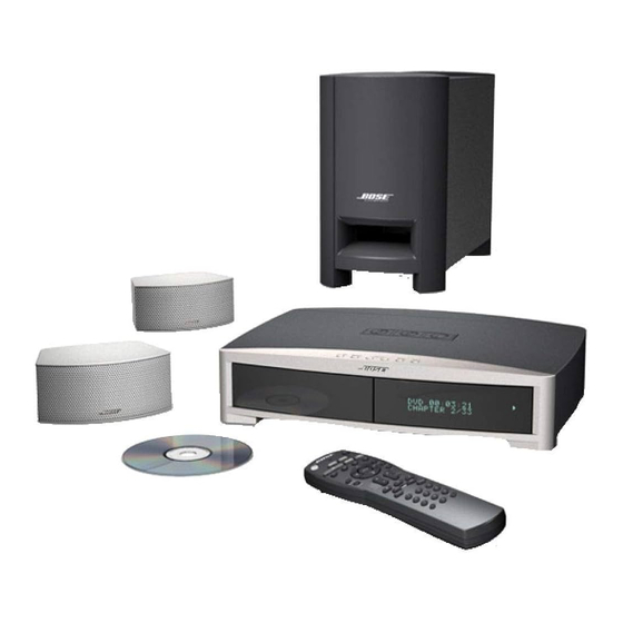
Bose 3-2-1 Manual de resolução de problemas - Página 18
Procurar online ou descarregar pdf Manual de resolução de problemas para Sistema de cinema em casa Bose 3-2-1. Bose 3-2-1 28 páginas. Home entertainment system
Também para Bose 3-2-1: Manual do Proprietário (44 páginas), Manual de configuração rápida (1 páginas)

THEORY OF OPERATION
6.4 AM Tuner
The signal from the external AM loop antenna enters through the 2.5 mm AM jack, J2000 [sheet
1, D8], and is fed to the AM front end module, T2000 [D6]. The antenna input is balanced by
placing C2000 [D7] between one side of the input and ground, reducing electric field interfer-
ence. The front end module contains the varactor-tuned RF and Local Oscillator (LO) tracking
circuits. This part is pre-tuned by the manufacturer for proper alignment with AM antenna
PT199824-002, and is further adjusted during factory alignment, if necessary. The RF tuned
output is fed to the AM buffer FET transistor Q2002 [D6] and the buffered output is sent to pin
27 of U2000 [C3] which contains the AM RF amplifier, mixer, IF amplifier, AM detector, and AM
S-meter circuitry. The 450 kHz AM IF output signal that appears on pin 2 is filtered by the IF
filter, T2001 [C5], and fed back into the IC on pin 4. The AM IF signal is demodulated by U2000
and the audio output is sent to pins 20 and 21, to pass through the low pass filter used in FM for
de-emphasis.
In order to avoid having harmonics of the main board switching power supplies interfere with the
AM tuner the switching frequency is controlled by F_SYNCH, a clock output from U3 [console
schematic sheet 14, C4] on the main board. The signal Supply_Freq_Sel (via lookup table
based on AM station) is used to vary the output of F_SYNCH between two frequencies that will
avoid the selected channel frequency and its image the best.
The AM seek stop processing and factory alignment is performed in a similar fashion to FM
mode processing. The nominal AM stop level is 56 dBµV/m @ 1080 kHz.
6.5 Phase-locked Loop Tuning
The AM and FM local oscillators are controlled by the PLL IC, U2074 [sheet 2, C3]. The micro-
processor selects the AM or FM band and the particular frequency. The 7.2 MHz clock refer-
ence is generated by the microprocessor which is the stable crystal oscillator frequency divided
by 2. The 7.2 MHz oscillator is divided down to produce a 12.5 kHz reference frequency in FM
mode and a 10 kHz (9 kHz for European and Japan units) reference frequency in AM mode.
U2074 [sheet 2, C/D3] divides down the AM or FM LO input, compares it to the appropriate
reference frequency and generates an error signal that is output on pin 19.
This error signal is integrated and amplified by an active lead-lag filter formed using an internal
FET inside U2074 and associated components connected to pins 19, 20 and 21. C2096, C2097,
R2079, R2080 and R2081 control the gain and pole-zero locations of the filter. The values of
these components are chosen to ensure stability of the PLL while providing sufficient speed,
moderate overshoot, and symmetric up/down settling time. The resulting signal output at pin 21
is used as a tuning voltage and is fed back to the AM and FM front-ends.
The AM tuning voltage is further filtered by R2078 and C2095 and is fed back to the common
node of the varactors inside the AM front end, T2004. The tuning voltage varies the capaci-
tance of the varactor diodes, which in turn simultaneously tunes both the AM antenna and the
AM LO. In FM mode, the tuning voltage is filtered by R2077 [sheet 2, D1] and the input capaci-
tance of pin 5 of the FM front-end (0.047uF) [sheet 1, B/C8]. As in the AM case, the tuning
voltage is fed to varactors which tune the LO frequency and RF filtering.
18
