Bose Acoustimass 3 Series Manual de serviço - Página 7
Procurar online ou descarregar pdf Manual de serviço para Sistema estéreo Bose Acoustimass 3 Series. Bose Acoustimass 3 Series 42 páginas. Powered speaker system
Também para Bose Acoustimass 3 Series: Manual do Proprietário (17 páginas), Manual do Proprietário (10 páginas), Manual (43 páginas)
NOTE: The following discussion references the AM-3P EQ and Amplifier schematics and
block diagrams. The block diagrams,Figures 3 and 4, can be found on page 5 and the
schematics are located in the back of this service manual.
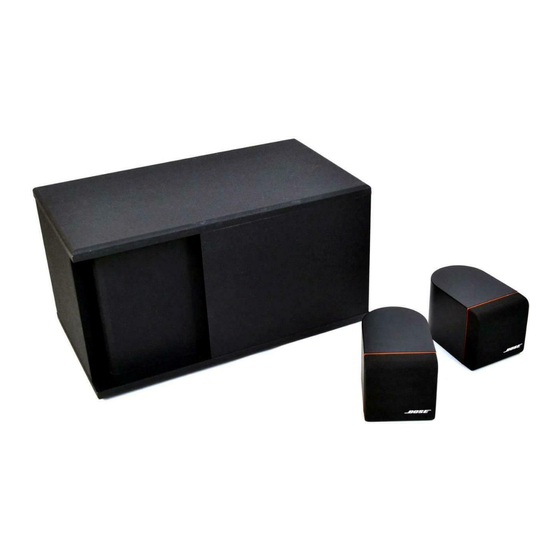
The AM-3P powered Acoustimass loudspeaker system is designed to be used with the BOSE
Lifestyle Music Center (or other line level audio source) to form a simple, yet complete, home
audio system. The AM-3P is based acoustically on the AM-3 Acoustimass (unpowered)
loudspeaker system. The AM-3P, like its big brother, the AM-5P, offers many advantages over
a separately powered AM-3 system. These include:
-
Automatic turn-on/ turn-off (mute) of the amplifier output stage
-
Automatic (BOSE patented) dynamic equalization
-
Bi-amplification for better power distribution to speakers
-
Active equalization for smoother frequency response
-
Amplifier short-circuit and DC offset fault protection
-
Local volume/sensitivity control
-
Bass/treble room compensation controls
-
Differential input stage (to reject hum)
-
Dynamic compressor to prevent amplifier output overload distortion
NOTE: In the discussion of L/R (left/right) channels,only the right channel is discussed. The left
channel operation is identical.
1. Power Supply
A single, universal, 115/230V EI core power transformer is used to power the system. It has
been specially designed for minimum magnetic flux leakage and stand-by power consumption.
The transformer primary remains energized (always on) except when the power switch is in the
off position.
The two primary windings of the transformer are wired in series for 230V operation, and in
parallel for 115V operation, depending on the position of the customer accessible voltage
select switch. If the system is accidentally energized at 230V with the switch in the 115V
position, the replaceable fuse (F1 located on the Equalizer PCB assembly), will open the
circuit within 2 minutes. This will be the only damage to the system.
AM-3P THEORY OF OPERATION
BLOCK DIAGRAM DESCRIPTION
GENERAL
6