DROPSA 1524175 Series Manual de operação e manutenção - Página 3
Procurar online ou descarregar pdf Manual de operação e manutenção para Bomba de água DROPSA 1524175 Series. DROPSA 1524175 Series 8 páginas. Pneumatic pumps for grease

5. PUMP COMPONENTS
•
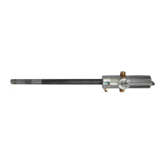
GREASE DIP PIPE
DISASSEMBLY OF GREASE DIP PIPE
Lock the pumping element in a vice with soft metal jaws: the locking point must be the valve body (64). With a stud with a
diameter of 10, unscrew the connector part of the dip pipe (68). Remove the pump from the vice, lock the dip pipe and
unscrew it from the motor. Simultaneously using a number 10 Allen wrench, unscrew the nut (67). Remove the pumping
element (52) or (53) or (54) depending on the pump model. Carefully clean all the parts.
POS.
QTY.
50
1
Conjunction nut
51
3
Spring pin Ø 4 mm. (0.15 in.)
52
1
Dragging rod 480 mm. (18.9 in.)
53
1
Dragging rod 740 mm. (29.1 in.)
54
1
Dragging rod 940 mm. (37 in.)
55
1
Extension 480 mm. (18.9 in.)
56
1
Extension 740 mm. (29.1 in.)
57
1
Extension 940 mm. (37 in.)
58
1
Pressure by-pass valve spring
59
1
Pressure by-pass valve sphere
60
1
Pumping piston
61
2
O-ring 3075
62
1
Cylinder
63
1
Valve
64
1
Valve body
65
1
Filter
66
1
Grease pusher washer
67
1
Nut
68
1
Dip pipe
69
1
O-ring 3056
70
1
O-ring 3037
DESCRIPTION
3
