Daikin AGZ Manual de instalação e manutenção - Página 9
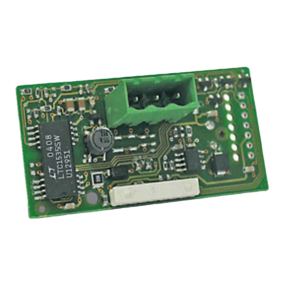
Procurar online ou descarregar pdf Manual de instalação e manutenção para Controlador Daikin AGZ. Daikin AGZ 12 páginas. Microtech ii chiller modbus communication module
Também para Daikin AGZ: Manual de instalação e manutenção (14 páginas)

Set up the Unit for Network Control
After the communication module has been installed, the next
step is to configure the unit controller for network control. The
BAS protocol must first be set to Modbus using either the
MicroTech II chiller unit controller keypad/display or operator
interface touch screen (OITS) as described below.
Network Setup for Centrifugal Chillers
1. Disable the chiller. The chiller should not be operating
while performing this procedure.
2. At the chiller unit controller keypad display:
a. Change the Set/Unit Setpoint menu Protocol = to
Modbus.
NOTE: If using the OITS panel, in the SETPOINTS/MODE
screen, set the #9 setpoint = to Modbus.
b. Enter the password of "2001."
c. As needed in the Set/Unit Setpoint menu, change
Source = to Network.
NOTE: If using the OITS panel: as needed in the
SETPOINTS/MODE screen, change the #3 setpoint,
Control Source = to BAS.
3. Re-enable the chiller.
4. Verify that the chiller is operational from the BAS
interface.
Network Setup for all other Chillers
1. Disable the chiller. The chiller should not be operating
while performing this procedure.
2. At the chiller unit controller keypad display:
a. Set the Protocol = to Modbus in the applicable
menu screen.
b. Use
Table 1
to determine the operator password
for the specific chiller model.
c. Enter the password.
3. As needed in the Set/Unit Setpoint menu, change
Source = to Network.
4. Re-enable the chiller.
5. Verify that the chiller is operational from the BAS
interface.
Once the BAS protocol has been set, proceed to the next
section to set network addressing parameters.
www.DaikinApplied.com
Table 1: Password Menu Screen
Model
AGZ-A
ACZ-A
AGZ-B
AGZ-C
ACZ-B
AGS-A
AGS-B
AGS-C
AGS-D
WGS
WMC WSC
WDC WCC
WPV HSC
HDC TSC
WGZ/TGZ
Note: Chiller models AGZ-A/B, ACZ-A/B, WGZ, and TGZ have a single unit
controller. Models AGS-B/C and WGS have one unit controller with multiple
circuit controllers. Unit settings for AGS-B/C and WGS models are adjusted
from the unit controller.
Modbus Network Addressing
This section describes Modbus network requirements, followed
by instructions on how to configure the communication module
for BAS integration.
Modbus Network Considerations
Network Topology
The unit controller and communication module follow standard
Modbus network rules. The network is a daisy-chain of Modbus
controllers including all slaves and the master. The Modbus
standard recommends that the network be terminated on
each end with the characteristic impedance of the network
of 120 ohms. Follow the guidelines stated in the Modbus
specifications (www.Modbus.org).
Addressing and Establishing Communications
Valid slave nodes addresses are in the range of 0 – 247
decimal. The individual slave devices are assigned addresses
in the range of 1 – 247. A master addresses a slave by placing
the slave address in the address field of the message. When
the slave returns its response, it places its own address in the
response address field to let the master know which slave is
responding. Address 0 is the broadcast address. When the
address is 0, all slaves respond to the message.
9
IM 743-7 • MICROTECH II CHILLER UNIT CONTROLLER
Network Configuration
Menu Screen
Password
12
2001
6
2001
9
2001
7
2001
12
8945
16
8453
17
8745
15
8745
14
2001
10
2001
Network Configuration
