Daikin R32 Split Series Manual de instalação - Página 13

Procurar online ou descarregar pdf Manual de instalação para Ventilador Daikin R32 Split Series. Daikin R32 Split Series 17 páginas. R32 split series
Também para Daikin R32 Split Series: Manual de instalação (16 páginas), Manual de instalação (16 páginas), Manual de instalação (16 páginas), Manual de instalação (17 páginas), Manual de instalação (16 páginas), Manual de instalação (20 páginas), Manual de instalação (14 páginas), Manual de instalação (14 páginas), Manual de operação (16 páginas), Manual de operação (16 páginas), Manual de operação (8 páginas), Manual de instalação (17 páginas), Manual de instalação (16 páginas), Manual de instalação (20 páginas), Manual de instalação (20 páginas), Manual de instalação (16 páginas), Manual de instalação (16 páginas), Manual de instalação (14 páginas), Manual de instalação (14 páginas), Manual de instalação (16 páginas), Manual de instalação (17 páginas), Manual de instalação (20 páginas), Manual de instalação (13 páginas)
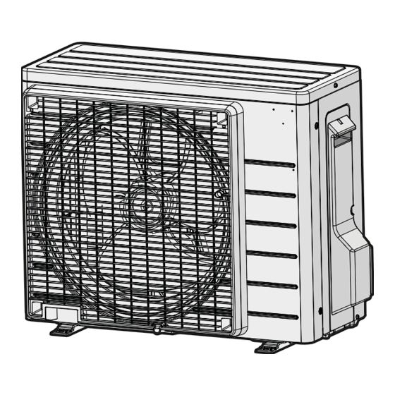
Daikin R32 Split Series Manual de instalação
Indoor Unit Installation
6.

Drain piping

1) Connect the drain hose, as described right.
2) Remove the air filters and pour some water into the drain pan to check the water flows
smoothly.
3) If drain hose extension or embedded drain piping is required, use appropriate parts that match the hose front end.
[Figure of hose front end]
4) When extending the drain hose, use a commercially
available extension hose with an inner diameter of
16mm. Be sure to thermally insulate the indoor section of
the extension hose.
5) When connecting a rigid polyvinyl chloride pipe
(nominal diameter 13mm) directly to the drain
hose attached to the indoor unit as with
embedded piping work, use any commercially
available drain socket (nominal diameter 13mm)
as a joint.

Refrigerant Piping Work

1.
Flaring the pipe end
1) Cut the pipe end with a pipe cutter.
2) Remove burrs with the cut surface facing
downward so that the chips do not enter the pipe.
3) Put the flare nut on the pipe.
4) Flare the pipe.
5) Check that the flaring is properly made.
WARNING
• Do not use mineral oil on flared part.
• Prevent mineral oil from getting into the system as this would reduce the lifetime of the units.
• Never use piping which has been used for previous installations. Only use parts which are delivered with the unit.
• Never install a dryer to this R32 unit in order to guarantee its lifetime.
• The drying material may dissolve and damage the system.
• Incomplete flaring may cause refrigerant gas leakage.
English
16
18
Drain hose supplied
with the indoor unit
18
Drain hose supplied
Commercially available drain
with the indoor unit
socket
(nominal diameter 13mm)
(Cut exactly at
right angles.)
Set exactly at the position shown below.
Flare tool for
A
R410A or R32
Clutch-type
Die
A
0-0.5mm
Flare's inner surface
must be flaw-free.
The drain hose should
be inclined downward.
No trap is permitted.
Do not put the end
of the hose in water.
Extension drain hose
Indoor unit
drain hose
16
Heat insulation tube
(field supply)
Commercially available rigid
polyvinyl chloride pipe
(nominal diameter 13mm)
Remove burrs.
Flaring
Conventional flare tool
Clutch-type
Wing-nut type
(Rigid-type)
(Imperial-type)
1.0-1.5mm
1.5-2.0mm
Check
The pipe end must
be evenly flared in a
perfect circle.
Make sure that the
flare nut is fitted.
11