Daikin R32 Split Series Manual de instalação - Página 14

Procurar online ou descarregar pdf Manual de instalação para Ventilador Daikin R32 Split Series. Daikin R32 Split Series 16 páginas. R32 split series
Também para Daikin R32 Split Series: Manual de instalação (17 páginas), Manual de instalação (16 páginas), Manual de instalação (16 páginas), Manual de instalação (16 páginas), Manual de instalação (17 páginas), Manual de instalação (16 páginas), Manual de instalação (20 páginas), Manual de instalação (14 páginas), Manual de instalação (14 páginas), Manual de operação (16 páginas), Manual de operação (16 páginas), Manual de operação (8 páginas), Manual de instalação (17 páginas), Manual de instalação (20 páginas), Manual de instalação (20 páginas), Manual de instalação (16 páginas), Manual de instalação (16 páginas), Manual de instalação (14 páginas), Manual de instalação (14 páginas), Manual de instalação (16 páginas), Manual de instalação (17 páginas), Manual de instalação (20 páginas), Manual de instalação (13 páginas)
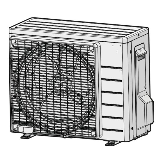
Daikin R32 Split Series Manual de instalação
13 Disposal
13
Disposal
NOTICE
Do NOT try to dismantle the system yourself: dismantling
of the system, treatment of the refrigerant, oil and other
parts MUST comply with applicable legislation. Units
MUST be treated at a specialised treatment facility for
reuse, recycling and recovery.
INFORMATION
To protect the environment, make sure to perform an
automatic pump down operation when relocating or
dismantling the unit. For the pump down procedure, refer
to the service manual or the installer reference guide.
14

Technical data

▪ A subset of the latest technical data is available on the regional
Daikin website (publicly accessible).
▪ The full set of latest technical data is available on the Daikin
Business Portal (authentication required).
14.1

Wiring diagram

The wiring diagram is delivered with the unit, located inside of
the outdoor unit (bottom side of the top plate).
14.1.1

Unified wiring diagram legend

For applied parts and numbering, refer to the wiring diagram on the
unit. Part numbering is by Arabic numbers in ascending order for
each part and is represented in the overview below by "*" in the part
code.
Symbol Meaning
Symbol Meaning
Circuit breaker
Connection
,
Connector
Earth
Field wiring
Fuse
Indoor unit
INDOOR
Outdoor unit
OUTDOOR
Residual current
device
Symbol
Colour
Symbol
BLK
Black
ORG
BLU
Blue
PNK
BRN
Brown
PRP, PPL
GRN
Green
RED
GRY
Grey
WHT
SKY BLU Sky blue
YLW
Symbol
A*P
Installation manual
14
Protective earth
Protective earth (screw)
A
Rectifier
,
Relay connector
Short-circuit connector
Terminal
Terminal strip
Wire clamp
Colour
Orange
Pink
Purple
Red
White
Yellow
Meaning
Printed circuit board
Symbol
BS*
BZ, H*O
C*
AC*, CN*, E*, HA*, HE*, HL*,
HN*, HR*, MR*_A, MR*_B, S*, U,
V, W, X*A, K*R_*, NE
D*, V*D
DB*
DS*
E*H
FU*, F*U, (for characteristics,
refer to PCB inside your unit)
FG*
H*
H*P, LED*, V*L
HAP
HIGH VOLTAGE
IES
IPM*
K*R, KCR, KFR, KHuR, K*M
L
L*
L*R
M*
M*C
M*F
M*P
M*S
MR*, MRCW*, MRM*, MRN*
N
n=*, N=*
PAM
PCB*
PM*
PS
PTC*
Q*
Q*C
Q*DI, KLM
Q*L
Q*M
Q*R
R*
R*T
RC
S*C
S*L
S*NG
S*NPH
S*NPL
S*PH, HPS*
S*PL
Meaning
Pushbutton ON/OFF, operation
switch
Buzzer
Capacitor
Connection, connector
Diode
Diode bridge
DIP switch
Heater
Fuse
Connector (frame ground)
Harness
Pilot lamp, light emitting diode
Light emitting diode (service
monitor green)
High voltage
Intelligent eye sensor
Intelligent power module
Magnetic relay
Live
Coil
Reactor
Stepper motor
Compressor motor
Fan motor
Drain pump motor
Swing motor
Magnetic relay
Neutral
Number of passes through ferrite
core
Pulse-amplitude modulation
Printed circuit board
Power module
Switching power supply
PTC thermistor
Insulated gate bipolar transistor
(IGBT)
Circuit breaker
Earth leak circuit breaker
Overload protector
Thermo switch
Residual current device
Resistor
Thermistor
Receiver
Limit switch
Float switch
Refrigerant leak detector
Pressure sensor (high)
Pressure sensor (low)
Pressure switch (high)
Pressure switch (low)
RXJ42+50A
R32 split series
3P512025-12X – 2021.12