Daikin McQuay 910121754 Dados de instalação e manutenção - Página 9
Procurar online ou descarregar pdf Dados de instalação e manutenção para Acessórios Daikin McQuay 910121754. Daikin McQuay 910121754 16 páginas. Digitally adjustable display sensor for water source heat pumps smartsource gs series; smartsource gt series; with microtech iii controls enfinity cch series; enfinity ccw series; enfinity vfc series; enfinity vfw series; enfinity lvc series; enfinity lvw

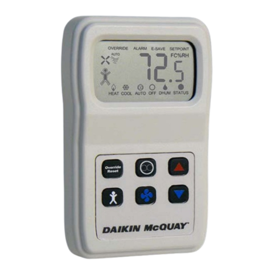
Display Descriptions
Fan Status & Speed Indicators:
The Fan Shape, 4 Wavy Lines and "Auto" word
indicate Fan and Speed status.
"Fan & No Wavy Lines" indicate the fan is Off.
"Fan & 2 Wavy Lines" indicate Low.
"Fan & 3 Wavy Lines" indicate Medium.
"Fan & 4 Wavy Lines" indicate High, and the
word "Auto" indicate fan Auto mode.
System Mode "Heat/Cool/Auto/Off/Dhum"
Indicators:
The "Heat/Cool/Auto/Off/Dhum" Mode Indicators on the
bottom of the display describe each of the sensor's modes.
The mode is changed by pushing the System Mode button on
the sensor. (Dhum is only used on WSHP units.)
Alarm Word On The Display:
The "Alarm" word indicator on top illuminates when the
sensor interprets the "Status" input code from the controller
as an alarm. See
Table 4 on page
E-Save Word On The Display:
The "E-Save" word indicator on top illuminates when the
sensor interprets the "Status" input code from the controller
as Standby Mode (See
Table 4 on page
Setpoint Word On The Display:
The "Setpoint" word on top illuminates when the sensor is
displaying the setpoint on the numerical display (Tempera-
ture or Humidity). When this "Setpoint" indicator is off, the
numerical display shows the actual room temperature or
humidity.
Status Word & Dot On The Display:
The Status "Dot" on the display indicates the unit status or
alarm condition. It is turned "On" and "Off" by interpreting
the status input from the controller on terminal 1. See
3 on page
5.
Table 4
shows the alternating conditions and sensor status.
9.
9).
Figure
Table 4: WSHP unit status input timing definition
Status Dot
Status Dot "ON"
"OFF" (0 vdc)
(+ 5 vdc) time
Time
0.5 seconds
0.5 seconds
0.0 seconds
Continuous
0.5 seconds
5.5 seconds
5.5 seconds
0.5 seconds
0.0 seconds
Continuous
Table 5: Fan Coil (FCU) unit status input timing definition
Status Dot
Status Dot "ON"
"OFF" (0 vdc)
(+ 5 vdc) time
Time
0.3 seconds
0.3 seconds
0.0 seconds
Continuous
0.5 seconds
5.5 seconds
5.5 seconds
0.5 seconds
0.0 seconds
Continuous
3.0 seconds
3.0 seconds
WSHP
Display
Availability
Indication
Controller Off (or
Network
"ALARM" On
"Wink" operation
active)
Unit running in
Night
Setback Override
"OVERRIDE" On
Mode or
no power to the
unit
Hollow Occupied
Unoccupied
Mode
Icon
"E-SAVE" On
Standby Mode
Solid Occupied
Occupied Mode
Icon
Fan Coil
Display
Availability
Indication
"ALARM" On
Alarm Active
Unit running in
Night
Setback Override
"OVERRIDE" On
Mode or
no power to the
unit
Hollow Occupied
Unoccupied
Mode
Icon
"E-SAVE" On
Standby Mode
Solid Occupied
Occupied Mode
Icon
Calibration
Mode/Network
No Change
Wink
IM 1171-3 / Page 9 of 16
