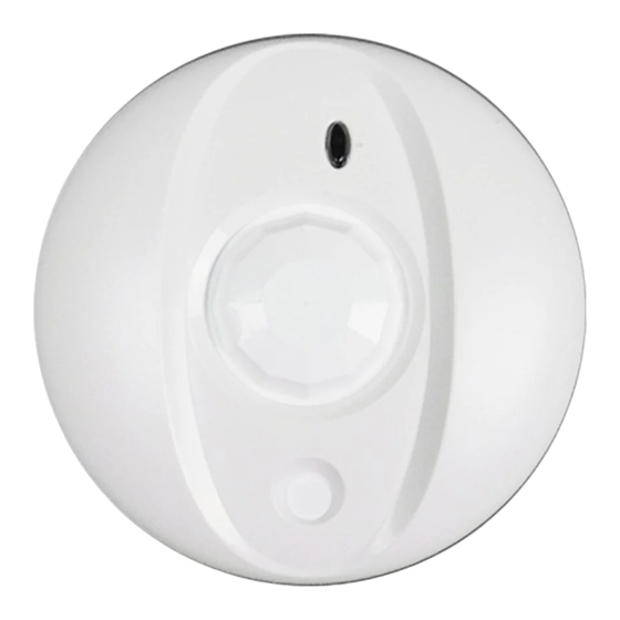
DSC BV-501 Instruções de instalação
Procurar online ou descarregar pdf Instruções de instalação para Sensores de segurança DSC BV-501. DSC BV-501 2 páginas. Ceiling mount pir detector

INSTALLATION INSTRUCTIONS
INSTALLATION INSTRUCTIONS
The Bravo5 is a ceiling mount detector designed to
provide reliable motion detection for residential
and commercial applications. The Bravo5 uses a
special Fresnel lens made for 360° detection in
conjunction with a quad element PIR sensor
optimized for uniform detection all around its field
of view. Special attention is given to false alarm
immunity against RF, static, electrical transient to
ensure trouble free operation for many years.
Features
• Multi-Level Signal Processing
*
• 360° coverage
• Quad element PIR sensor
• High level static and transient protection
• Excellent RF immunity
• Temperature compensation
• Fast/Slow detection jumper
• LED ON/OFF jumper
• SMD construction
• Super quiet operation
• 5 year warranty
Specifications
Electrical
• Input Voltage: 9 - 14.5 V
DC
• Current (nominal): 18 /15 mA (alarm on/off) @12 V
Contact Rating
• Alarm Relay: 0.1A @24V
DC
• Tamper Switch: 0.1A @24V
DC
Size (diameter x height)
4.6" x 1.4" / 117 mm x 36 mm
Operation
• Maximum detection range (diameter)
Ceiling Mount
Detector placed 8 ft./ 2.4 m from floor: 24 ft./ 7.3 m
PIR Detector
Detector placed 10 ft./ 3.0 m from floor: 30 ft./ 9.2 m
Detector placed 12 ft./ 3.6 m from floor: 40 ft./ 12.2 m
• Additional operating modes
LED ON/OFF Jumper J1
Pulse count (fast/slow) Jumper J2, J2 ON is fast count.
Environmental/Immunity
• RF Immunity: 20V/m ( 100Hz - 1.2GHz)
• Transients @ wiring terminal: 2.4KV @ 1.2joules
• Operating temperature: 32 -122°F / 0 - 50°C
• Humidity 5 - 95% RH non-condensing
Product Information
• BV-500: Form 'A' alarm contact
• BV-501: Form 'A' alarm contact and tamper switch
• BV-502: Form 'C' alarm contact and tamper switch
Coverage
Top View (at 8 ft./ 2.4 m height)
Side View
DC
*
Patented
Locating the Detector
The Bravo5 is designed to be mounted on the ceiling of a
dry indoor location for 360° coverage. Ensure that the
expected path of an intruder is perpendicular to the beam
path. Use the coverage pattern indicated on the coverage
diagram to determine the best sensor location.
Survey the mounting location and the area being protected
for the following potential problems. Avoid the following
sources of false alarms:
Reflective Surfaces
Do not aim the detector at reflective surfaces such as
mirrors or windows as this may distort the coverage pattern
or reflect sunlight directly onto the detector.
Air Flow
Avoid locations that are subject to direct high air flow such
as near an air duct outlet.
Moisture
Do not locate the detector near sources of steam or oil.
The Sun
Do not aim the detector such that it will receive direct sunlight.
Obstructions
Do not limit the coverage by placing large objects within the
detection area (such as plants, high shelves, filing cabinets etc.).
Mounting
To open the case, insert a small screwdriver in the tab
restraining clip. Gently pry tab downward and twist the top
cover counter-clockwise and lift it up from the bottom cover.
Use a small screwdriver to remove the appropriate
knockouts for wiring. Mount the bottom cover using the
screws supplied.
To close the case, use the locating line on the bottom cover
to align the tab on the top cover. Once the top cover is
engaged, twist the top cover clockwise to lock it in place.
NOTE: Since no adjustment is necessary for the circuit
board, it is not recommended that the installer remove the
circuit board from the case.
