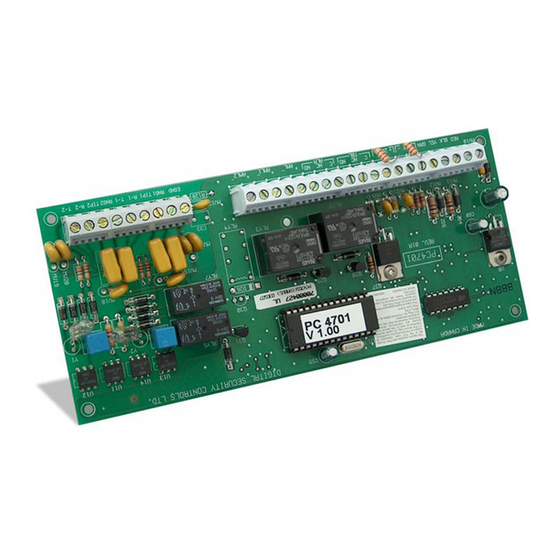
DSC Maxsys PC4701 Instruções de instalação
Procurar online ou descarregar pdf Instruções de instalação para Unidade de controlo DSC Maxsys PC4701. DSC Maxsys PC4701 2 páginas. Fire expansion module

1.
Introduction
The PC4701 is a fire expansion module for use with PC4010CF/
PC4020CF Maxsys security systems. One module may be
installed per system.
NOTE: The PC4701 cannot be used on a Maxsys system if an
Escort4580 is also connected.
2.
Specifications
• Connects to control panel via 4-wire Combus
• Current Draw: 40 mA (from Combus)
• Class B / Style B 2-Wire Smoke Detector Supervision
• Operating Voltage Range: 8.9-12.0 V
• Maximum Alarm Current: 80mA
• Maximum Ripple: 0.5 VP-P
• Compatibility Identifier: FM1
• Maximum line resistance: 50Ω
• Class B / Style B Waterflow Supervision
• Supervised Dual Telephone Lines
• Service Type: Automatic, Manual, Sprinkler Supervisory,
Waterflow
• Signaling Type: Non-Coded
3.
Installing the PC4701
3.1 Unpacking
The PC4701 package includes the following parts:
• One PC4701 circuit board
• 2 listed end-of-line resistors (2200 ohms)
• Four plastic stand-offs
3.2 Mounting
Install the PC4701 on either side-wall of the PC4010CF/
PC4020CF cabinet, mounted in a dry, secure location.
Perform the following steps to mount the unit:
1. Press the four plastic stand-offs through the mounting holes
on the side wall of the cabinet.
2. Secure the cabinet to the wall in the desired location. Use
appropriate wall anchors when securing the cabinet to drywall,
plaster, concrete, brick or other surfaces.
3. Press the circuit board into the plastic stand-offs to secure the
module to the cabinet.
Once the unit is mounted, complete the wiring.
3.3 Wiring
Before beginning to wire the unit, ensure that all power (AC
transformer and battery) is disconnected from the control panel.
Perform the following steps to complete wiring:
Please refer to the System Installation Manual for information on limitations regarding product use
and function and information on the limitations as to liability of the manufacturer.
PC4701 Fire Expansion Module
1. Connect the four Combus wires to the PC4701. Connect the
red, black, yellow and green Combus wires to the RED, BLK,
YEL and GRN terminals, respectively.
2. Complete all other wiring according to the wiring diagrams
above.
Common Fire Trouble Contact
If the Common Fire Trouble Contact is connected, the output will
activate when any of the following troubles occur:
• Fire Zone Trouble
• Any Bell Trouble
• Any AC Trouble
DC
• Any Battery Trouble
• Ground Fault Trouble
• Communication Troubles
The output will deactivate when all trouble conditions are
restored. Refer to the PC4010/PC4020CF Installation Guide for
more information on these trouble conditions.
Common Fire Alarm Contact
If the Common Fire Alarm Contact is connected, the output will
activate when an alarm occurs on any fire zone. The output will
deactivate when all fire zones have been successfully reset.
Telephone Line Switching
When the PC4701 detects a TLM trouble on either telephone line,
it will automatically use the other telephone line if a
communication needs to be sent. If there are no TLM troubles,
the PC4701 will use telephone line 1, leaving telephone line 2
available for the premises telephones.
3.4 Applying Power
After all wiring is completed, apply power to the control panel.
Connect the battery leads to the battery, then connect the AC
transformer. For more information on control panel power
specifications, see the control panel Installation Manual.
NOTE: Do not connect the power until all wiring is complete.
4.
Enrolling the Module
Once all wiring is complete, the module must be enrolled on the
system. To enroll the module, perform the following:
1. Enter installer's programming by pressing [*] [8] [Installer's
Code].
2. Scroll to "Module Hardware" and press the [*] key.
3. Scroll to "Enroll Module" and press the [*] key.
4. Scroll through the different modules until "PC4701 Fire" is
displayed. Press the [*] key. After this is done, the keypad
displays the module number and confirms enrollment (e.g.
"PC4701 Fire Mod 01 Enrolled").
Installation Instructions
