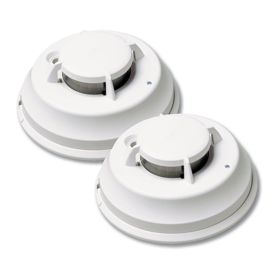
DSC FSA-410DLRST Instruções de instalação e de utilização
Procurar online ou descarregar pdf Instruções de instalação e de utilização para Alarme de fumo DSC FSA-410DLRST. DSC FSA-410DLRST 4 páginas. Fsa-410d series

FSA-410D Series Smoke Alarm
Installation and Operating Instructions
Read this instruction sheet thoroughly before installation and use of the FSA-410D Smoke Alarm
Piezo Sounder
Introduction
The FSA-410D is a 4-wire photoelectric smoke alarm with
optional: fixed temperature heat detector, auxiliary form C relay,
and/or remote LED output.
Operation
Approximately every 7 to 8 seconds the unit tests for a smoke or
heat alarm condition. During this sequence the unit also performs
self diagnostics, and checks for faults. During normal operation
the LED will remain on to indicate energization of the unit and the
sounder will not sound.
Smoke Alarm
The smoke detector has a nominal fixed alarm sensitivity (refer to
Specifications on back page) and it will go into alarm when the
signal level exceeds the 'alarm' threshold. During an alarm the
LED will shut off, the sounder will sound continuous beeps and
the alarm relay will be activated.
Remote Alarm - Interconnection
Multiple alarms can be connected using the PRM-4W Polarity
Reversal Module. When a fire alarm occurs, the unit will signal the
Installer Instructions
1. Smoke Alarm Placement
On smooth ceilings, units may be spaced 9.1m (30 ft) apart as a
guide. Other spacing may be required depending on ceiling
height, air movement, the presence of joists, uninsulated ceilings,
etc. Refer to CAN/ULC-S553-02 for installation recommendations.
LED/Test Button
Alignment Marks
Do NOT locate smoke alarms at
the top of peaked or gabled ceil-
ings; the dead air space in these
locations may prevent the unit
from detecting smoke. Avoid areas
with turbulent air flow, such as
near doors, fans or windows.
Rapid air movement around the
detector may prevent smoke from
entering the unit.
Do NOT locate units in areas of
high humidity.
PRM-4W to reverse the polarity of the 4-wire loop. This will acti-
vate the sounders of all units connected on the loop. Refer to the
PRM-2W/4W Installation Manual for installation details.
Smoke - Drift Compensation
The unit automatically compensates for long-term environmen-
tally induced changes to maintain a constant smoke sensitivity.
When the drift compensation has reached its high or low limit of
adjustment, the unit will go into the trouble state.
Heat Alarm
The heat detector will go into alarm when the heat signal level
exceeds the heat alarm threshold (135ºF/57ºC). During an alarm
the LED will shut off. The sounder will sound continuous beeps
and the alarm relay will be activated.
Alarm Restore
When the smoke clears from the unit and the heat signal falls
below the 'restore' level, the unit will automatically reset itself.
Alarm Indications
Condition
Normal/Sensitivity in
Production Range
Smoke Alarm
Heat Alarm
Alarm Restore
Remote Alarm
Low Power Trouble
Other Fault / Trouble
Test Switch - Failed
Test Switch - Pass
A = Activated / D = Deactivated
NOTE: For models FSA-410DFIS, the relay is deactivated, for all
other models the relay is activated during the condition.
Do NOT locate units in areas where the temperature rises above
38ºC (100ºF) or falls below 5ºC (41ºF).
2. Mount Smoke Alarm Backplate
Mount backplate on standard 4" octag-
Locking
onal electrical box using the screws pro-
Tab
vided.
NOTE: Power must be supplied from a
ULC Listed power supply or alarm con-
trol unit auxiliary output. Install wiring
in accordance with the appropriate
national and local electrical codes.
Mounting Holes
CAUTION: The dust cover protects the
unit when not in service. Remove the
dust cover before use.
Alarm Aux.
Relay
LED
Sounder
FormA
ON
OFF
D
OFF
Steady
See Note
OFF
Steady
A
ON
OFF
D
ON
Steady
D
ON
OFF
D
ON
CHIRP 1/50s
D
ON
CHIRP 1/50s
D
OFF
Steady
A
Relay
FormC
D
A
See Note
D
D
D
D
D
A
