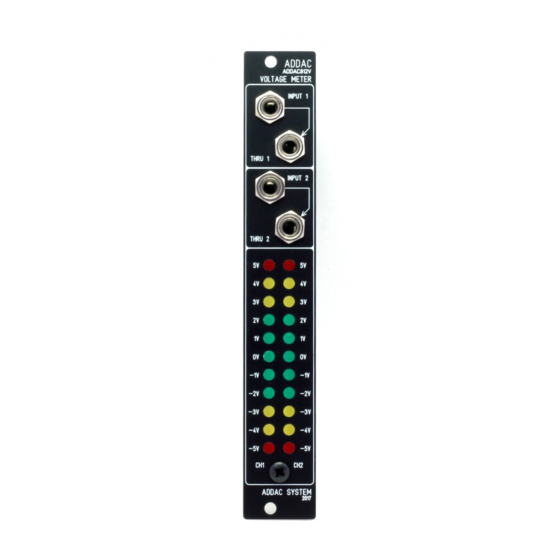
ADDAC System ADDAC812V Manual de montagem - Página 4
Procurar online ou descarregar pdf Manual de montagem para Sintetizador ADDAC System ADDAC812V. ADDAC System ADDAC812V 12 páginas. Voltage meter

ADDAC812V Assembly Guide
STEP 5:
Place the four jacks in the pcb and attach the front panel. Hold the front panel in place by tightening the
bottom screw. Also tighten the jack nuts and solder one leg of the top jack, this will keep the front panel
secure to the pcb.
STEP 6:
Allign all leds in their holes, the top red leds may need to be adjusted slightly with a tweezer.
STEP 7:
To help soldering the leds with the flat top matching the panel, have a few a standard
business/credit/debit cards at hand and place them between the last nut and the bottom screw.
ADDAC SYSTEM
page 4
