3onedata ES7110-2GS-4F-P Manual do utilizador - Página 2
Procurar online ou descarregar pdf Manual do utilizador para Interruptor 3onedata ES7110-2GS-4F-P. 3onedata ES7110-2GS-4F-P 5 páginas. Managed industrial ethernet switch
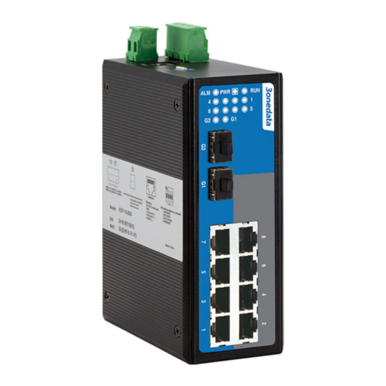
1. DIP switches for default factory
2. Console port
3. 2-pin terminal block for relay output
4. Ground screw
5. Power input terminal block
6. Screw holes for Wall Mounting Kit
7. DIN-Rail mounting kit
8. Power indicator
9. System running LED
10. Relay alarm LED
11. Link/ACT LEDs
12. Gigabit SFP port
13. 10Base-T /100Base-TX Ethernet port
14. 100Base-FX fiber port
Power supply input
DC Series Switch:
The product top panel provided 4 bit power supply input terminal
block, support DC input. DC power supply input supported
redundancy function, provided PWR1 and PWR2 power input,
can use for single, and can connect 2 separately power supply
system, use 1 pair terminal block connect the device at the same
time. If one of the power systems broke, the device can work
un-interruptible.
Built-in
overcorrect
connection protection. Voltage input range is 12
terminal block defined as: V1- V1+ V2- V2+ .
AC Series Switch:
The Industrial Ethernet switches have singe power and
redundancy power two kinds of power input. The singe power AC
series
top
panel
provides
3
bit
100~240VAC/DC power entered (L/+, FG, N/-)
Important notice:
1. Power ON operation: first of all, insert power cable's terminal
block into device's power port, then insert power supply plug into
power source
2. Power OFF operation: First off all, unpin power plug, then
strike the terminal block, please take care of operation sequence.
Dimension
The series of products are the same size, and the number of the
Ethernet interface is different. Unit (mm)
- 2 -
DIP Switch
protection,
Reverse
48VDC
Top panel provided 4 bits DIP switch to do function configure
ON to enable effective ,1 and 4 keep for future function. 2 is
recovery default factory. 3 is for upgrade. Please power off and
power on when you change the status of DIP switch.
Relay connection
Relay access terminals in the top panel of the device. Between the
terminal
block
for
two terminal relay, as an open circuit state in normal non alarm
state, when there is any alarm information to the closed state. The
two terminal block connector are used to detect both power failure
and port failure. The two wires attached to the Fault contacts form
an open circuit when the device has lost power supply from one of
the DC power inputs or one of the ports is failure. (Note: The AC
power switch does not support power alarm.)
Console port
This series product provided 1pcs procedure test port based in
serial port. It adopts RJ45 interface, located in top panel, can
configure related command through RJ45 to DB9 female cable.
Communication connector
10/100BaseT(X) Ethernet port
The pinout define of RJ45 port display as below, connect by UTP
or STP. The connect distance is no more than 100m. 100Mbps is