3onedata IES2220-16T4GS-2P48 Manual de instalação rápida
Procurar online ou descarregar pdf Manual de instalação rápida para Interruptor 3onedata IES2220-16T4GS-2P48. 3onedata IES2220-16T4GS-2P48 3 páginas. Unmanaged industrial ethernet switch
IES2220 Series
Unmanaged Industrial Ethernet
Switch Quick Installation Guide
3onedata Co., Ltd.
Address:
3/B, Zone 1, Baiwangxin High Technology
Industrial
Park,
Xili,
Shenzhen
Website:
www.3onedata.com
Tel:
+86 0755-26702688
Fax:
+86 0755-26703485
【Package Checklist】
Please check whether the package and accessories are
intact while using the switch for the first time.
1.
Industrial Ethernet switch
3.
DIN-Rail mounting attachment
If any of these items are damaged or lost, please contact
our company or dealers, we will solve it ASAP.
【Product Overview】
This series are unmanaged DIN-Rail industrial Ethernet
switches. Models as follows:
Model I. IES2220-16T4GS-2P48 (16 100M copper ports +
4 Gigabit SFP slots + 2 48VDC power supplies)
Model II. IES2220-16T4GS-P220 (16 100M copper ports
+ 4 Gigabit SFP slots +1 220VAC power supply)
Model III. IES2220-16P4GS-2P48-120W (16 100M PoE
copper ports + 4 Gigabit SFP slots + 2 48VDC
power supplies + 120W POE power)
Model IV. IES2220-16P4GS-2P48-200W (16 100M PoE
copper ports + 4 Gigabit SFP slots + 2 48VDC
power supplies + 200W POE power)
Model V. IES2220-16P4GS-2P24-120W (16 100M POE
copper ports + 4 Gigabit SFP slots +2 24VDC
power supplies +120W POE power)
Model VI. IES2220-8T8P4GS-2P48-120W (8 100M
copper ports + 8 100M PoE copper ports + 4
Gigabit SFP slots + 2 48VDC power supplies
+120W POE power)
Model VII. IES2220-8T8P4GS-2P48-200W (8 100M
copper ports + 8 100M PoE copper ports + 4
Gigabit SFP slots + 2 48VDC power supplies +
200W POE power)
Model VIII. IES2220-8T8P4GS-2P24-120W (8 100M
Nanshan
District,
copper ports + 8 100M PoE copper ports + 4
Gigabit SFP slots + 2 24VDC power supplies +
120W POE power)
【AC Panel Design】
Rear view, Bottom view and Top view
2.
Certification
4.
Warranty card
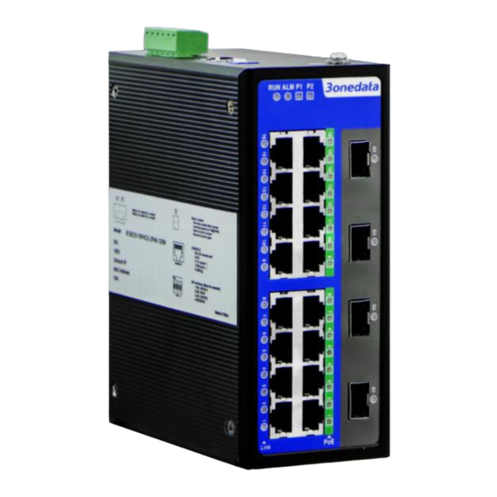
Front view and Side view
Model II
1.
Wall-mounting location hole
2.
DIN-Rail mounting kit
3.
AC power input terminal block
4.
Relay alarm output terminal block (reserved)
5.
Console port (reserved)
6.
DIP switch (reserved)
7.
Grounding screw
8.
Device running indicator RUN
9.
Relay alarm indicator ALM (reserved)
10.
Power input status indicator PWR
11.
100M copper port connection indicator
12.
100M copper port
13.
Gigabit SFP slot
14.
Gigabit SFP connection indicator
【DC Panel Design】
Rear view, Bottom view and Top view
Front view