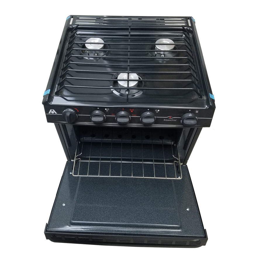
Atwood CA Instalação, operação e manutenção - Página 6
Procurar online ou descarregar pdf Instalação, operação e manutenção para Placa de fogão Atwood CA. Atwood CA 8 páginas. Lp gas range & slide-in cooktops
Também para Atwood CA: Manual de instalação e operação (8 páginas), Instalação, operação e manutenção (10 páginas), Manual de instalação, operação e manutenção (16 páginas), Instruções de instalação, operação e manutenção (8 páginas)

E-
CABINET
&
COUNTER CUT OUT
CHART
CABINET
&
COUNTER CUT OUT CHART
.
TABLEAU DE
DECOUPE
DES ELEMENTS ET DU
COMPTOIR
RECESSED
BI.FOLD
COVER
t
Minimum
clearance
t0
combustible
materials.
(typical
tlvo
(2) sides and
back)
t
Eloignement minimum
des mat6riaux
combustibles .(Typiquement sur
les deux
c6tes
et a
l'arridre)
N0TE: Maximum countertop overhang
=
3/4"
N0TE: rebord maximum du c0mptoir
=
1
I
mm
RECESSED
BI-FOLD
COVER
-
GOUVERCTE
PTIANT EN DEUX PABTIES
ENCASTRE
Notch
for
N-Series
only
All
Slide-ln Cooktops
Recessed Bi-Fold
Covei
CUT OUT DIMENSIONS
DIMENSIONS DE
tA
OECOUPE
A
B
c
(BV/CV)
D
E
F
G
17"
Ranges
S6rie 17"
.75'
1MM
ZU.ZA
51 4MM
1.131
29MMt
16'
406Nlr,1
0'
0[.,1[il
1.75'
45Ntr.r
1.5"
3BNu
21"
Raflges
S6rie
21
"
1E'
I
Ml\i]
20.25'
514wrrr
1.131
29H,rtr,rt
20"
508wu
0'
0uru
1.75"
45MM
1.5"
211Ruu
Sl
ide-ln
S6rie e encaslremenl
l./7
451
MUr
20.25'
514r,1M
1.13',1
29H,turt
a'
76uN
0'
0wH.r
1.75"
45uHlt
1.5"
38r,rvr
'17"
N-Series
S6rie
43cm
N-Series
7.75"
51ruM
20.25"
514r,rtul
1.13',1
29Mtlt
tb
406Mr,1
7t16'
11MM
Ltc
45mu
t.5
38r.rnrr
21"
N-Series
36rie 53cm N-Series
51[,rM
20.25'
514[ir[/
1
.13',1
29mH,lt
20"
508uw
7116"
11un,t
t./J
45M[,
t.5
38uu
Slide-ln
N-Series
S6rie
i
encaslremenl N-Series
7.75'
51trtN
20.25'
51
4uu
1.131
9Ouu*
3'
7Ai^ii
ilto
1 aE'
45uw
l.c
iSuu
TAMINATE
MATERIAT
mrrERmu
srRlttrtE
MPD
PART
#
56397
BA AND RV
OVEN
17--
21'
CA
AND
CV
sUDE-tN
CUT OUT BIMENSIONS
-
DIMENSIONS DE LA
DECOUPE
114"
6mm
A
A
A
B
c
D
E
F
G
lb.u
406
mm
20.0'
508
mm
3.0"
76 mm
17.75- 20.0- 2.31'
24.5- 2]3'
20.25'
451
mm
508
mm
59
mm 622mm
54
mm
514
mm
1t32"
.8
mm
56391
16.0"
406
mm
20.0"
508
mm
3.0"
76 mm
17.75" 20.0'
1.84'
24.5"
2.13
20.25'
451
mm
508
mm
47
mm
622
mm
54
mm
514
mm
SCHEMATIC
DIAGRAM
FOR ELECTBONIC IGNITION
Burner
Valve
Switches
M
O
DELS
Thermostat Switch
o---
1
2
VOLT
DC
o*--
ELECTRICAL RATING:
CONNEC
'12
volt
Battery
f+-l
-
-
L]
TION DIAGRAM FOR ELECTBONIC
IGNITION
MOOELS
Burner
Valve
Swilches
Thermostat Switch (if equipped)
12 VDC.
0.05
A
For 12 VDC
service,
DO
N0T
connect
SPARKELECTB.DES
to
higher voltage. D0 N0T
connect
rcee
nr".
!!!!
to
a
circuit fused {or more than
3A
drdr\h..(
lgnition
Module
Top
Burners
H
G
W
=
RED
Wire
= GREEN
Wire
= WHITE
Wire
=
Wire Connection
=
Wired by lnstaller
Pilot
Burner
(il
--c--
-c---
----
-_T-
I
1r
CD
1i
,-]
l-'
RANGE HOOD MOUNTING
INFORMATION
A
Range
Top
19-3/8"
Mounting
Trim
Range
Top
Depth
Range
Top plus
0ven
Vent
D
3t4'
15-7
t8"
19-9t16'
6
