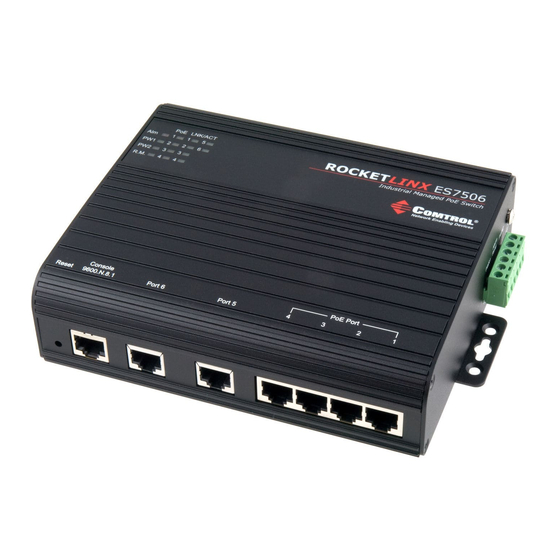
Comtrol ROCKET LINX ES7506 Manual de instalação rápida - Página 3
Procurar online ou descarregar pdf Manual de instalação rápida para Interruptor Comtrol ROCKET LINX ES7506. Comtrol ROCKET LINX ES7506 8 páginas. Industrial 6-port managed poe switch

1.
Insert the positive and negative wires into PW+ and PW- contacts (PW1
and PW2). You can connect a single power supply or two power supplies
depending on your requirements.
2.
If both power inputs are connected, the ES7506 is powered from the
highest connected voltage. The unit can be configured to signal an alarm
for loss of power in either PW1 or PW2.
3.
Tighten the wire-clamp screws to prevent the wires from being
loosened.
Power should be disconnected
from the power supply before
connecting it to the switch.
Otherwise, your screwdriver
blade can inadvertently
short your terminal
connections to the grounded
enclosure.
Wiring the Alarm Relay Output
The alarm relay output or digital
output (DO) contacts are on the
terminal block connector on the side of the ES7506. The power supply
should be UL Listed with a minimum output rating of 2.5A at 24-55VDC.
The relay contacts are energized (open) for normal operation and close
under faulty conditions. Faulty conditions can include power failure, Ethernet
port link break, or other predefined events configurable in the ES7506 user
interface. To activate the alarm relay output function, refer to the
RocketLinx ES7506 User Guide .
DC Power Input
Alm
PWR1
PWR2
+
+ -
-
12-24AWG
DC Power Output
12-24AWG
2
Power Supply
24-55VDC/2.5A
(UL Listed)
V-
24-55VDC
V+
Wiring Positive Power Supplies
Power Supply
24-55VDC/2.5A
(UL Listed)
V-
24-55VDC
V+
AC Power Input
AC Power Input
