Comtrol ROCKETLINX ES7110 Manual de instalação rápida - Página 3
Procurar online ou descarregar pdf Manual de instalação rápida para Interruptor Comtrol ROCKETLINX ES7110. Comtrol ROCKETLINX ES7110 6 páginas. Industrial poe switch
Wire the Power
Use the following procedure to wire the power and ground.
1. Disconnect the terminal block
from the ES7110.
2. Insert the positive and negative
wires (12-24AWG) into the
PWR+ and PWR- contacts.
Note: Power should be
disconnected from the power
supply before connecting it to
the switch. Otherwise, your
screwdriver blade can
inadvertently short your terminal connections to the grounded enclosure.
3. Tighten the wire-clamp screws to prevent the wires from coming loose.
4. Plug the terminal block into the ES7110.
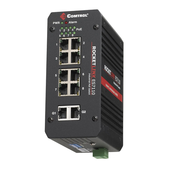
Wire the Relay Output and Ground
The ES7110 provides Relay Output. The relay contacts are energized (open) for normal
operation and will close under a faulty condition, such as, an Ethernet port link break.
The Relay alarm can be configured by the DIP switches.
1. Insert positive and negative
wires into Relay A and Relay B.
2. Tighten the wire-clamp screws
to prevent the wires from
coming loose.
3. Connect a ground wire
between the chassis and earth
ground using 12-24AWG wire
to ensure that the RocketLinx
ES7110 is not damaged by
noise or electrical shock.
a. Loosen the earth ground screw on the bottom of the RocketLinx ES7110 with a
screw driver.
b. Tighten the screw after the earth ground wire is connected.
DC Power output
12 to 24AWG
Wire
Relay PWR
Earth Ground
Port Alarm
2
Power Supply
Power Supply Requirements
ES7110
48VDC/96W (Min)
ES7110-VB 12-24VDC/96W (Min)
Maximum 1A/24VDC
Relay PWR
AC Power input
Alarm System
Extra Power
System