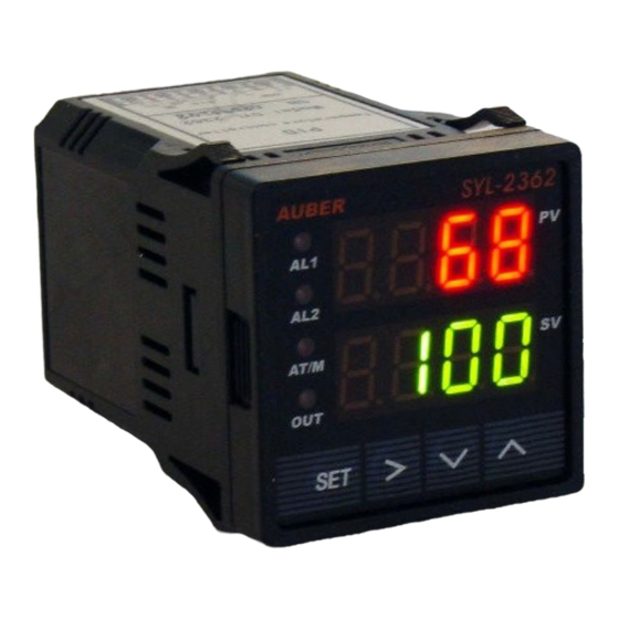
Auber Instruments SYL-2362A2 Manual de instruções - Página 2
Procurar online ou descarregar pdf Manual de instruções para Controlador de temperatura Auber Instruments SYL-2362A2. Auber Instruments SYL-2362A2 6 páginas.

AUBER INSTRUMENTS
4.1.2 RTD sensor
For a three-wire RTD with standard DIN color code, the two red wires should be
connected to the terminals 9 and 10. The white wire should be connected to
terminal 8.
For a two-wire RTD, the wires should be connected to terminals 8 and 9. Jump a
wire between terminals 9 and 10.
Set controller input type, Inty, to P100 (1° resolution) or P10.0 (0.1° resolution).
4.2 Power to the controller
The power cables should be connected to terminals 1 and 2. Polarity does not
matter. It can be powered by 85 -260V AC or DC power source. Neither a
transformer nor jumper is needed to wire it up. For the sake of consistency with
the wiring example described later, we suggest you connect the hot wire to
terminal 2 and neutral to 1. Since the controller is in a plastic shell, ground wire is
unnecessary.
4.3 Output connection
Two control output options are offered by this controller. (1) The SSR control
output provides an 8V DC signal that can control up to 4 SSRs in parallel. (2) The
J2 relay output can be used to turn on a contactor or a solenoid valve. It can also
drive a small heater directly if the heater draws <3 Ampere. For application that
needs two control outputs, such as one for heating and other for cooling, J1 relay
can be used for the second output with on/off control mode. Please note J1 can't
be used for main control output. Both J1 and J2 can be used as alarm output if
they are not used as control output.
4.3.1 Connecting the load through SSR
Connect terminal 7 to the negative input and terminal 6 to the positive input of the
SSR. Set the system output configuration, outy, to 2, 3 or 6 - depending on the
control mode used. See Figure 10 for details.
4.3.2 Connecting the load through a contactor
J1 relay is for alarm output only. Assuming the controller is powered by a 120V AC
source and the contactor has a 120VAC coil, jump a wire between terminal 2 and
14. Connect terminal 13 to one lead of the coil and terminal 1 to the other lead of
the coil. Set the system output configuration, outy, to 1, 4, or 5 -depending on the
control mode used. Please see Figure 11 ~ 14 for examples.
Note: For first time users without prior experience with PID controllers, the
following notes may prevent you from making common mistakes:
4.4.1 Power to the heater does not flow through terminal 1 and 2 of the controller.
The controller consumes less than 2 watts of power. It only provides a control
signal to the relay. Therefore, 20 gauge wires are sufficient for providing power to
terminal 1 and 2. Thicker wires may be more difficult to install.
4.4.2 The J1, J2 relays are "dry single pole switches". They do not provide power
by itself. Figure 11 shows how it is wired when providing a 120V output (or when
output has the same voltage as the power for controller). If the load of relay
requires a different voltage than that for the controller, an additional power source
will be needed (Please see the alarm wiring of Figure 10 and controller output J2
of Figure 12 for examples).
4.4.3 SSR output power does not come from the input of the SSR. The output of
the SSR is a single pole switch between terminal 1 and 2 of the SSR. The input of
the SSR is for control, or triggering the SSR. (Please note we are talking about the
SSR itself, not the SSR control output of the controller). Figure 10 shows how the
2021.10
SSR output should be wired. When switching a North American 240VAC power,
the heater will be live even when the SSR is off. Users should install a double pole
mechanical switch to the power input.
5. Parameter Setting
For safety reasons, the controller parameters are divided into three groups with
different pass codes. You should only give the code to those who have the
responsibility and knowledge of how to properly change it. Code 0089 contains the
parameters for system configuration that may need to change during the initial set
up. Code 0036 contains the parameters for tuning performance. Code 0001 is for
controlling temperature and alarm settings.
5.1 System Configuration Parameters (accessed by code 0089)
The system configuration parameters are listed in table 1. To change the
parameters, press SET key, enter code "0089" and press SET key again. Then,
follow the flow chart in Figure 3.
SET
SET
SET
Figure 3. System setup flow chart
(1) Press SET key to enter setting mode;
(2) Press >, V and ^ keys to enter parameters;
(3) Press SET key to confirm;
(4) Press V or ^ keys to select the new parameter.
Table 1. System configuration parameters
Code
Description
Inty
Input Sensor Type
Inty
outy
Control Output Mode
outy
Hy
Hysteresis Band
Hy
Atdu
Atdu
Autotune Offset
PSb
PSb
Input Offset
rd
Control Function
rd
CorF
Display Unit
CorF
End
End
Exit
Note 1. The controller is preset for K type thermocouple input. If any other type of
sensor is used, the Inty value needs to be changed to the corresponding symbol
as shown in Table 2.
WWW.AUBERINS.COM
SET
SET
SET
SET
SET
SET
SET
Setting Range
Initial
Note
See table2
K
1
0, 1, 2, 3, 4, 5, 6
2
2
0~9999
3
3
0~200(Deg)
10
4
-100~100(Deg)
0
5
0: heating 1: Cooling
0
0: ° C, 1: ° F
1
SET
SET
SET
SET
SET
SET
SET
P2/6
