3onedata SW4485I Manual do utilizador - Página 2
Procurar online ou descarregar pdf Manual do utilizador para Interruptor 3onedata SW4485I. 3onedata SW4485I 3 páginas.
Também para 3onedata SW4485I: Manual de instalação rápida (3 páginas)
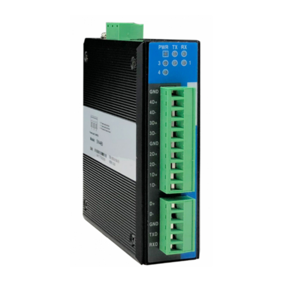
1. Power indicator
2. Host computer RS-232/485 transmits data indicator
3. Host computer RS-232/485 receive data indicator
4. Slave computer RS-485 Link/ACT indicator
5. Slave computer 4-port RS-485 terminal blocks
6. Host computer RS-232/485 terminal blocks
7. Ground screw
8. Power input terminal block
9. DIN-Rail mounting kit
【Power supply input】
The product provides 3 bits terminal block (1/V-, 2/GND, 3/V+),
V-, V+ is 12~48VDC power input. It can also work if connection
opposite.
【Dimension】
Unit (mm)
【Communication connector】
Serial port connection
Host computer RS-232/485 serial port
Host computer RS-232/485 serial port adopts 5bit terminal blocks
connector. The PIN defines is as follows, RS-232/485 port:
PIN
PIN define
Description
1
D+
RS-485+Signal input (out)
2
D-
RS-485-Signal input (out)
3
GND
Signal ground
4
TxD
RS-232 Transmit data
5
RxD
RS-232 Received Data
Slave computer RS-485 serial port
Slave computer 4 channel RS-485 serial port adopts 10bit
terminal blocks connector. The PIN defines is as follows, RS-485
port:
PIN
PIN define
Description
1
GND
Signal ground
2
4D+
RS-485+Signal input (out) for serial port 4
3
4D-
RS-485-Signal input (out) for serial port 4
4
3D+
RS-485+Signal input (out) for serial port 3
5
3D-
RS-485-Signal input (out) for serial port 3
6
GND
Signal ground
7
2D+
RS-485+Signal input (out) for serial port 2
8
2D-
RS-485-Signal input (out) for serial port 2
9
1D+
RS-485+Signal input (out) for serial port 1
10
1D-
RS-485-Signal input (out) for serial port 1
RS-485 Port fault alarm and protection
RS-485 port fault alarm and protection is the solution to connect
- 2 -
multiple RS-485 devices, an effective way to enhance its
reliability. The HUB device has 4 slave computer RS-485 serial
ports, and each port has reverse connect protection function, and
can work in shutdown mode. Any RS-485 port reverse connection
will only affect its RS-485 BUS system, will not affect the normal
work of other interface connected with RS-485 system. Users can
quickly determine fault port and other connected devices
according to the fault alarm light.
Note: The connection of slave computer RS-485 serial ports of the
same HUB device is wrong connection.
【LED Indicator】
LED indictor light on the front panel of product, the function of
each LED is described in the table as below.
System Indication LED
LED
Statue
Description
ON
Power is being supplied/working well
PWR
Power is not being supplied/ not
OFF
working well
Data is being transmitted
Blinking
TXD
OFF
No data is being transmitted
Blinking
Data is being received
RXD
OFF
No data is being received
Power is on the device, the
ON
corresponding interface of D1~D4 is on
the state of data receive/transmit
The corresponding interface of D1~D4
Blinking
1~4
is transmitting/receiving data
Fault alarm: Power is not on the device
or power is on the device but the
OFF
corresponding interface of D1~D4 is
reversed
【Installation】