3onedata 3012 Series Manual de instalação rápida - Página 2
Procurar online ou descarregar pdf Manual de instalação rápida para Conversor de multimédia 3onedata 3012 Series. 3onedata 3012 Series 3 páginas. 10/100/1000m media converter
Também para 3onedata 3012 Series: Manual do utilizador (4 páginas)
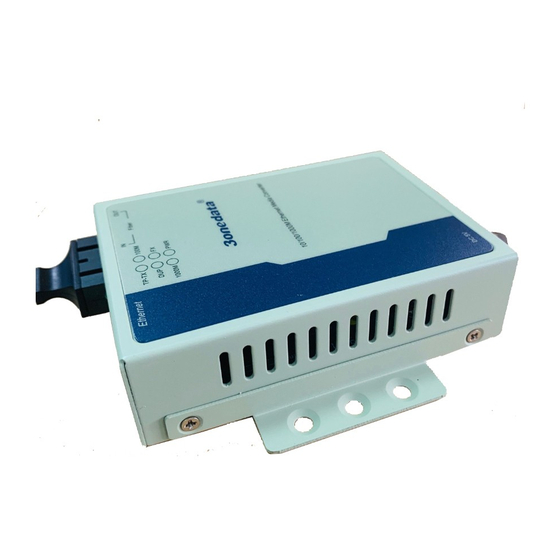
Model III
1.
Gigabit Ethernet fiber port
2.
Power supply indicator PWR
3.
Gigabit Ethernet fiber port indicator (FX / FX ACT)
4.
Ethernet copper port 100M speed indicator (100M)
5.
10M/100M/Gigabit Ethernet copper port indicator
(TP-TX / TP Link)
6.
Ethernet copper port duplex indicator (DUP)
7.
Ethernet copper port Gigabit speed indicator
(1000M)
8.
10M/100M/Gigabit Ethernet copper port
9.
5VDC Terminal block for power input
10.
Wall Mounting lug
11.
220VAC/DC power input outlet and switch
12.
Terminal block of -48VDC power supply input
13.
Reserved
【Mounting Dimension】
Unit: mm
Model I
Model II
Model III
Note Before Mounting:
Don't place or install the device in area near water or
moist, keep the relative humidity of the device
surrounding between 5%~95% without condensation.
Before power on, first confirm the supported power
supply specification to avoid over-voltage damaging the
device.
The device surface temperature is high after running;
please don't directly contact to avoid scalding.
【Wall-mounted Device Mounting】
Step 1
Place the device on the wall as reference or
reference installation dimension; mark 2 bolt
positions on the wall.
Step 2
Hang the device on the labeled wall; align the bolt
to the labeled position, then screw the bolt to
enhance stability, installation ends.
【Wall-mounted Device Disassembling】
Step 1
Device power off.
Step 2
Hold the equipment steady and unscrew the screw
on the wall
Step 3
Take out the device, disassembling ends.
Note before powering on:
Power ON operation: First insert the power supply
terminal block into the device power supply interface,
and then plug the power supply plug contact and power
on.
Power OFF operation: First, remove the power plug,
and then remove the wiring section of terminal block.
Please pay attention to the above operation sequence.
【Power Supply Connection】
5VDC power supply
Model I provides 1 DC round head for power supply
input and support 5VDC power supply.
220VAC/DC power supply
Model II provides 1 AC outlet with switch for
power supply input and support 220VAC/DC
power supply.
-48VDC power supply
Model III provides 3 5.08mm pitch terminal
block for power input, supports -48DC power
supply. The pin definition as follows:
PIN
1
2
PIN
FG
-48VDC+
definition
【Checking LED Indicator】
The device provides LED indicators to monitor the device
working status with a comprehensive simplified
troubleshooting; the function of each LED is described in the
table as below:
LED
Indicate
Description
PWR
PWR
ON
running normally
3
-48VDC-
is
connected
and