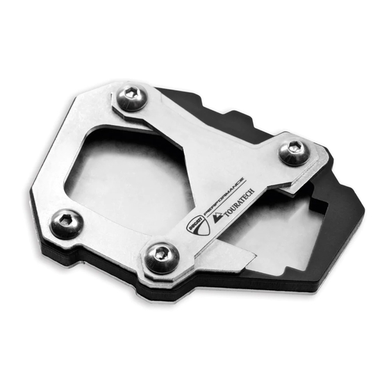
Ducati 97380331A Manual de instruções - Página 3
Procurar online ou descarregar pdf Manual de instruções para Acessórios para motociclos Ducati 97380331A. Ducati 97380331A 19 páginas. Stand extension plate kit for multistrada 1200

X
2
5 Nm ± 10%
4
6
Montaggio componenti kit
Importante
Verificare, prima del montaggio, che tutti i componenti risultino
puliti e in perfetto stato.
Adottare tutte le precauzioni necessarie per evitare di danneggiare
qualsiasi parte nella quale ci si trova ad operare.
Note
Per comprendere meglio il montaggio del kit, viene rappresentato
solo il gruppo cavalletto laterale.
Premontare i n.4 dadi speciali (5) sulla piastra inferiore (1) e sulla
parte superiore della piastra (1) montare la piastra distanziale (2).
Note
I dadi speciali (5) devono essere orientati con il collare (5A) rivolto
verso la piastra inferiore, come mostrato in figura (X).
Posizionare le piastre appena premontate nella parte inferiore della
base (A1) del cavalletto (A) fino a battuta.
Dal lato superiore, posizionare prima la piastra di chiusura inferiore
(3) e di seguito quella superiore (4), come mostrato in figura.
Impuntare le n.3 viti (6) e la vite (7).
Serrare le n.3 viti (6) e la vite (7) alla coppia indicata.
ISTR 661 / 00
5
1
5A
A
7
6
6
5 Nm ± 10%
2
A1
3
Kit installation
Caution
Check that all components are clean and in perfect condition
before installation.
Adopt any precaution necessary to avoid damages to any part of
the motorcycle you are working on.
Notes
To better understand how to install the kit, only the side stand unit
will be represented.
Pre-assemble no. 4 special nuts (5) on lower plate (1) and fix the
spacer plate (2) on the upper side of the plate (1) .
Notes
The special nuts (5) must be positioned with the collar (5A) facing
the lower plate, as shown in the figure (X).
Drive the pre-assembled plates fully home in the lower side of the
base (A1) of the stand (A).
From the upper side, position first the lower closing plate (3) and
then the upper closing plate (4), as shown in the figure.
Start no. 3 screws (6) and screw (7).
Tighten no. 3 screws (6) and screw (7) to the specified torque.
1
5
5
3
