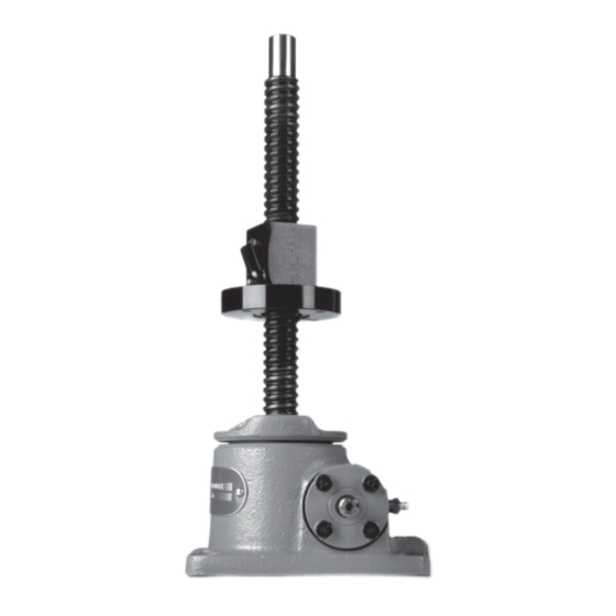
Duff-Norton UM98031 Instruções de instalação, operação e manutenção - Página 8
Procurar online ou descarregar pdf Instruções de instalação, operação e manutenção para Controlador Duff-Norton UM98031. Duff-Norton UM98031 16 páginas. Rotating ball screw actuators

long enough to extend 1 1/2˝ to 2˝ beyond
each end of the lifting nut.
Note
Apply tape to arbor O.D. at end away from ball
screw pilot to prevent lifting nut from accidentally
running off of arbor during disassembly (an O-ring
with a large cross section, stretched over the arbor,
is ideal for this purpose.)
Table 2-1. Dimensions Ball Nut Storage Arbor
Actuator
Ball Screw
Model No.
Root Dia. (in)
28632
9803
2803
98031
28031
28004/98004
9806
9811
98111
9821
9826
2861
b. Holding arbor firmly against shoulder of ball
screw pilot (5), unthread lifting nut (24) from
ball screw (5). As lifting nut bearing balls
disengage from ball screw grooves (5),
center lifting nut on arbor and remove arbor
from ball screw pilot.
Note
Lift arbor and lifting nut together, holding in
place to prevent lifting nut from sliding off of arbor.
c. Pass binding wire through arbor and bind
lifting nut and arbor together.
Note
Keeping assembly together in this manner will
eliminate the need for complete assembly of the
lifting nut during reassembly go the actuator. Com-
plete actuator disassembly as follows:
4. Remove pipe (4) from shell (3) [upright units] or
from shell cap (2) [inverted units].
Note
Some models have an expansion plug (4a) in
place of pipe (4). If the expansion plug must be
replaced, it will be removed later per Step 18.
5. Remove set screw (10 from shell cap (2) and
remove shell cap from shell (3).
Note
It may be necessary to tap shell (2) with a
hammer to loosen shell cap.
8
Arbor O.D. (in)
.480
.500
.820
.889
.820
.889
.870
.889
1.140
1.156
1.140
1.156
1.140
1.156
1.850
1.884
2.480
2.500
3.338
3.366
6. Remove ball screw (5) and gear assembly (6)
from shell. For ease in removing ball screw and
gear assembly, loosen cap screws (9) holding
flanges (11) and shift worm (14) slightly.
Note
On some models it may be necessary to remove
worm before moving ball screw and gear assem-
bly (see Step 7 and 8).
7. Remove top bearing (7) which may be attached
to either shell cap (2) or worm gear assembly
(6).
8. Remove cap screws (9), lockwashers (10) and
flanges (11).
Note
Be careful not to lose flange shims (12).
For 1/2-ton Models - Remove four set screws
(9a) from shell (3) and unthread bushings (11a)
from shell.
9. Remove worm (14) and worm bearings (15)
from shell (3) by striking end of worm shaft with
a soft-head mallet or hammer.
For 1/2-Ton Model - Remove worm (14) with needle
bearings (15a) and races (15b) from shell (3)
and remove needle bearings and races from
worm.
10. Remove bottom load bearings (8) which may be
attached to either shell (3) or gear (6).
11. Press oil seals (13) out of flanges (11).
12. Remove bearings (15) from worm (14) with
puller or press.
Note
This step is not necessary if worm (14) or
bearings (15) are not damaged.
13. Remove set screw (21) from locknut (20).
Note
Some models may not utilize a set screw.
14. Restraining ball screw (5) from turning (use soft
jaws), remove locknut (20) from ball screw (5).
Note
If all parts are to be reused, match-mark end of
screw and locknut so that they can be reas-
sembled in the same order.
15. Remove worm gear (6) from ball screw (5).
Note
It may be necessary to tap on worm gear as-
sembly to remove it. Use a soft face hammer.
Do not tap on gear teeth.
