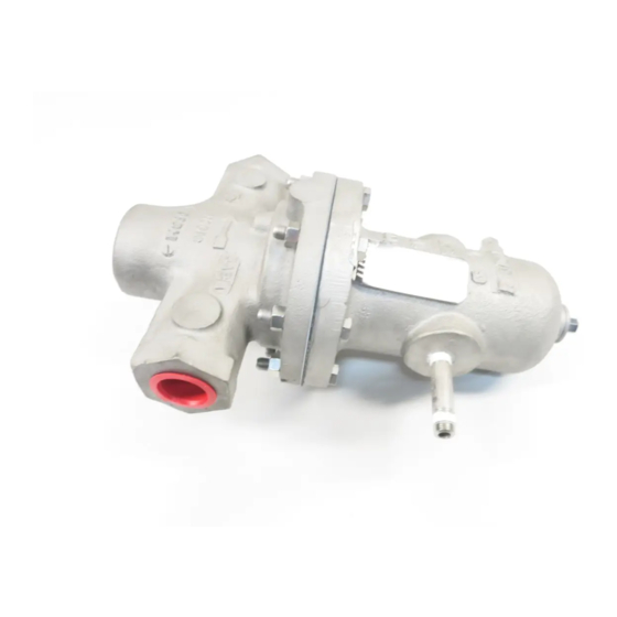
cashco DA2 Manual de instalação, operação e manutenção - Página 4
Procurar online ou descarregar pdf Manual de instalação, operação e manutenção para Controlador cashco DA2. cashco DA2 16 páginas. Direct-acting, positive bias differential pressure reducing regulator

VI. SHUTDOWN
Loading Pressure should be lowered as described
in Section III, paragraph 9 before shutting down the
system pressure.
1. To prevent force imbalances and possible di a-
phragm failure of the standard diaphragm con-
struction, the loading pressure (P
lowered until the loading pressure (P
than 50% of the diaphragm proof rating for the
VII.
MAINTENANCE
A. General:
1. The regulator may be serviced without re mov-
ing the regulator from pipeline. The regulator
is designed with quick-change trim to simplify
maintenance.
2. Record the nameplate information to
requisition spare parts for the regulator. The
in for ma tion should include: Size, Product Code
and Serial Number.
3. Refer to Section VIII for recommended spare
parts. Only use original equipment parts sup-
plied by Cashco for re build ing or re pair ing
regulators.
4. Owner should refer to owner's procedures for
removal, handling, cleaning and disposal of
nonreuseable parts, i.e. gaskets, etc.
NOTE: On regulators originally suplied as Spe-
cial Cleaning Option-55, -56, or -57, mainte-
nance must include a level of cleanliness equal
to Cashco cleaning standards of #S-1134,
#S-1542, and #S-1589 respectively. Con tact
factory for details.
5. The Inner Trim is re moved and replaced in the
body ( 23) as an assemblage of parts. The
Inner Trim Assembly, here in af ter called ITA,
consists of the following parts depending on
what dynamic sealing system the regulator is
using:
4
CAUTION
) should be
Load
Load
SECTION VI
standard construction. System se quenc ing
must ensure this oc curs.
2. It is recommended that manual operation not be
attempted by a bypass valve during a shutdown.
3. When the outlet pressure (P
to 5 - 10 psig, the inlet (upstream) block valve
may be closed. The inlet pressure (P
) is less
then decay to zero psig before the outlet (down-
stream) block valve is closed.
SECTION VII
Item
No.
13 ..................... All ..........................Guide Bearing/Piston
14 ..................... All ............................... StaticStem Seal †
14.1 ............... All ................... Upper Static Stem Seal †
14.2 ............... All ...................Middle Static Stem Seal †
14.3 ............... All ................... Lower Static Stem Seal †
15 ..................... All ................................ Cage O-ring Seal
16 .................CW,PW .............................................. Wiper
17.1 ..............CW,PW ................................. Wiper Washer
17.2 ........... OR,CP,PR ........ Camber Adjusting Washer *
17.3 ................. UC ..................................... Seal Retainer
19 ..................... All ................................................... Cage
20 ..................... All ...........................................Valve Plug
21 ..................... All ............................................ Seat Ring
27 ..................... All ............................. Dynamic Side Seal
27.1 ........... CP,CW ................................. TFE Cap Seal
27.2 ...........CP, CW ............................. O-ring Energizer
27.3 .............. UC .......... U-Cup Seal w/Metal Energizer
27.4 .............. OR ....................................... O-Ring Seal
27.5............PR,PW.....Piston Ring Seal w/Metal Energizer
* Metal Diaphragm Only.
† Comp. Diaphragm Only.
A detailed view of the dynamic side seal parts is
shown in Figure 1 on the next page.
SYSTEM UNDER PRESSURE. Prior to per form ing
any maintenance, isolate the reg u la tor from the
sys tem and relieve all pressure. Failure to do so
could result in personal injury.*
* Includes external sensing connection if applicable.
) has been lowered
2
Dynamic
Seal Type
Part Description
WARNING
) should
1
IOM-DA2
