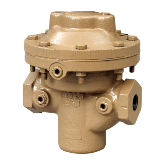
cashco DA6 Manual de instalação, operação e manutenção - Página 5
Procurar online ou descarregar pdf Manual de instalação, operação e manutenção para Controlador cashco DA6. cashco DA6 18 páginas. Direct-acting, pressure loaded back pressure regulator

B. Main Valve Disassembly:
WARNING
SYSTEM UNDER PRESSURE. Prior to per form ing
any maintenance, isolate the reg u la tor from the
system and relieve all pressure. Fail ure to do so
could result in personal injury.
1. Shut down the system in accordance with
Section VI.
2. Disconnect the external sensing line, if in-
stalled.
3. Though it is possible to disassemble the valve
unit while installed in a pipe line, it is rec om-
mend ed that main te nance be done in a shop
when pos si ble. The descriptions hereafter will
assume shop dis as sem bly. Remove valve
from pipe line.
4. Place the valve unit in a vise with the cover
dome (25) upwards.
5. Loosen the diaphragm flange bolts (11) and
nuts (12) uniformly.
6. Place matchmarks on body (23) and cover
dome (25) flang es. Completely remove bolt ing
(11,12). Remove the cover dome (25).
7. Grasp opposite edges of diaphragm (9) and
withdraw the ITA from within the cage (19).
Set the ITA aside.
8. Evenly loosen the cage cap screws (18) in
single revolution in cre ments until fully loos-
ened; remove cage cap screws (18).
9. Pull cage (19) up and out of body.
10. Remove o-ring cage seal (15).
11. Remove lower cage gasket (21).
12. If supplied, remove internal sensing drilled
plug (32) using 5/32" (4 mm) Allen key wrench.
NOTE: Valves with "Large Internal Sensing"
will not be equipped with any plug (32,33).
13. For metal diaphragm constructions, remove
diaphragm gasket (37) from body (23) di a-
phragm flange.
14. Remove body (23) from vise. Solvent clean
all removed metal parts.
IOM-DA6
C. Disassembly of the ITA:
1. Body Sizes 1/2" – 2". (See Figures 2 thru 5):
a. Obtain two pieces of square-section
barstock with a 3/8" - 7/16" dimension,
approximately 2 inches long.
b. Place plug into a vise using the bars of
a. above positioned on "flats" located on
plug (20) to prevent vise jaw marks from
direct surface contact with the plug (20).
Orient with diaphragms on topside.
c. Sizes 1/2" – 1":
locknut (7) by rotating CCW.
Sizes 1-1/4" – 2": Remove diaphragm
cap screw (7) by rotating CCW.
d. Remove upper diaphragm pressure plate
(8).
e. Remove diaphragm(s) (9, 9.1, 9.2, 9.9).
Examine diaphragm(s) to determine
wheth er failed; determine if operating
con di tions are ex ceed ing pressure drop
or temperature limits.
f.
For composition diaphragm construction,
remove upper stem seal (14.1).
g. For metal diaphragm construction, re move
lower pusher plate gasket (14.4).
h. Remove lower diaphragm pusher plate
(10).
i.
Remove middle stem seal (14.2).
j.
Remove plug (20) from vise, rotate end-
for-end, and resecure in vise using same
metal bars of a. above.
k. Loosen seat nut (30) CCW (viewed from
above) ap prox i mate ly two (2) rev o lu tions.
l.
Remove assembly (20, 27, 28, 29, 30)
from vise. Complete removal of seat disc
nut (30), seat disc washer (29), and seat
disc (28).
2. Body Sizes 2-1/2" – 4". (See Figure 6):
a. Place seat disc nut (30) into a vise with
the plug (20) oriented vertically. Do NOT
over-tighten nut (30) in vise.
b. Place closed-end hex wrench onto di a-
phragm locknut (7). Place socket wrench
on 3/4" hex upper end of plug (20). Loos en
diaphragm locknut (7) while holding plug
(20) from rotating by socket wrench.
Remove diaphragm locknut (7) after fully
loosened and socket wrench is removed.
c. Remove upper diaphragm pressure plate
(8).
d. Remove diaphragm(s) (9, 9.1, 9.2, 9.9).
Examine diaphragm(s) to determine
wheth er failed; determine if operating
con di tions are ex ceed ing pressure drop
or temperature limits.
Remove diaphragm
5
