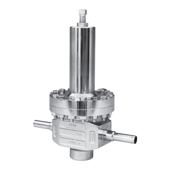
cashco SA1 Manual de instalação, operação e manutenção - Página 6
Procurar online ou descarregar pdf Manual de instalação, operação e manutenção para Controlador cashco SA1. cashco SA1 12 páginas. Ultra high purity, spring loaded pressure reducing regulators

c. Pressurize the regulator's inlet with
50–100 psig (3.5–6.9 Barg) of UHP grade
GN2.
d. Place a thin, flexible membrane that more
than covers the diaphragm flange cavity
of the body (23).
e. Using a soft-headed mallet (rubber,
leath er), sharply rap the thin membrane
over the top,center end of the piston-guide
bear ing (13). (Note: Gas will escape as
the plug (20) is momentarily forced off
the seat ring (21). Allow suf fi cient time
for leak age pres sure on outlet side to
bleed-off.) The ham mer rap should be
strong enough to "bounce" the plug (20)
into the seat ring (21), leav ing a "coined"
seating chamfer. Repeat a minimum of
2 times. Check after each rap to see if
re quired shut off is obtained.
f.
After "coining" is complete, remove UHP
grade GN2 pres sure source, membrane
and open out let.
7. To Install Diaphragm(s):
a. Install a new metal C-ring seal (28) into
the body (23) diaphragm flange groove.
b. Center diaphragm(s) (9) onto body's (23)
diaphragm flange.
c. Position upper diaphragm pressure plate
(8) centered on top of diaphragm(s) (9)
with cup upwards.
8. Place a small amount of light lithium grease
onto the adjusting screw (1). Insert both the
ad just ing screw (1) and its lock nut (2) into the
spring chamber (4). Allow the end of adjusting
screw to protrude into interior approximately
1/2 inch (12 mm).
9. Place range spring (6) centered on upper
di a phragm pressure plate (8).
10. Place a small amount of light lithium grease
into the recess of the spring follower (5). In-
stall washers (14) on spring follower. Place
the spring follower (5) on upper end of range
spring (6).
11. Aligning matchmarks and bolt holes, place
spring chamber (4) over range spring (6).
If spring chamber flange rests on body (23)
flange without a gap, remove spring chamber
and rotate ad just ing screw (1) deeper into
spring cham ber cavity another 1/4 inch (6
mm). Repeat this pro ce dure until the adjusting
screw (1) keeps the two flanges from touching
by ap prox i mate ly 1/8 inch (3 mm). NOTE: If
6
flang es do not come to geth er equal ly, the
upper di a phragm pres sure plate (8) may be
off-center. Remove spring cham ber (4) and
reposition upper di a phragm pres sure plate (8)
until the spring chamber comes down evenly
on all sides.
12. Install all flange bolts (12) and nuts (11) with
nameplate (99) located under one bolt head.
Hand-tighten nuts (11).
13. Evenly tighten body bolting (11,12) using an
alternating cross pattern in one revolution
increments. Tighten to the following torque
value: All body sizes: 30-35 Ft-lbs (41-47 Nm).
G. Pressure Testing:
1. If a high static pressure test is performed,
pres sure must be applied to all three of spring
chamber, inlet and outlet of body at the same
level.
DO NOT HIGH STATIC PRESSURE TEST
THE BODY WITH OUT SPRING CHAMBER
PRES SUR IZED. NOT ADHERING WILL DO
PHYSICAL DAMAGE TO INTERNALS THAT
COULD REN DER THE UNIT INOPERABLE.
MAX PRES SURE IS _______ psig (_______Barg).
2. Seat Leakage Test.
a. Release all range spring (6) force by
back ing out adjusting screw (1) fully.
b. Pressurize inlet to 50 psig (3.5 Barg) with
UHP grade GN2.
c. Tube outlet to a beaker of water to ob-
serve number of escaping gas bubbles.
A steady flow of gas bubbles (e.g., 20
bub bles / minute or greater) is ex ces sive
leakage.
3. Excessive leakage will require disassembly,
examination of sealing elements, correction of
problem, reassembly and retesting. Leakage
path may be via plug/seat or dynamic side
seal.
NOTE: If disassembly and re-testing is
required, the metal C-ring seal (28) MUST
be re placed for each disassembly/re as-
sem bly.
IOM-CA1/SA1
