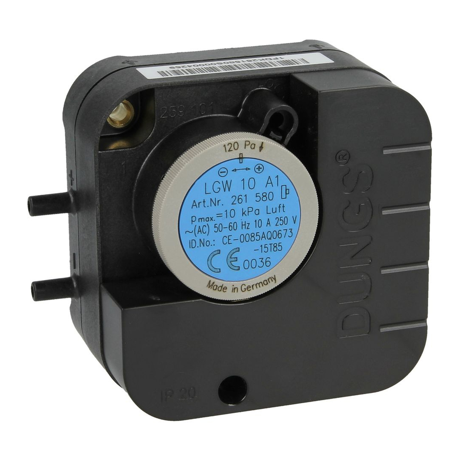
Dungs LGW 3 A1 Instruções de utilização e montagem - Página 3
Procurar online ou descarregar pdf Instruções de utilização e montagem para Interruptor Dungs LGW 3 A1. Dungs LGW 3 A1 6 páginas. Differential pressure switch for air, flue gas and waste gas factory-adjusted

Elektrischer Anschluß
IEC 730-1 (DIN EN 60 730 T1)
Berührschutz ist
nicht grundsätz-
lich gewährleistet,
Kontakt mit span-
nungsführenden
Teilen möglich!
Zur Erhöhung der Schaltleistung
wird bei DC-Anwendungen
< 20 mA und 24 V der Einsatz eines
RC-Gliedes empfohlen.
Druckanschluß
Geeignete Schläuche (für Luft,
Rauch- und Abgase) einsetzen.
Schlauchinnendurchmesser A
max. 4,0 mm
Schlauchaußendurchmesser B
max. 10 mm
Schläuche gegen unbeabsich-
tigtes Abziehen sichern: Kabel-
binder oder Schlauchschelle
oder Ω - Schelle.
A
B
Ersatzteile / Zubehör
Spare parts / Accessories
Pièces de rechange / access.
Parti di ricambio / Accessori
Berührschutz BS 1 / IP 10
BS 1 / IP 10 shock protection
Protection contre les contacts
accidentels BS 1 / IP 10
Protezione di contatto BS 1 / IP 10
Berührschutz BS 3 / IP 20
BS 3 / IP 20 shock protection
Protection contre les contacts
accidentels BS 3 / IP 20
Protezione di contatto BS 3 / IP 10
Haube komplett IP 42
IP 42 hood, complete
Capot complet IP 42
Calotta completa IP 42
3 ... 6
Electrical connection
IEC 730-1 (DIN EN 60 730 T1)
There is no protec-
tion against ac-
cidental contact.
Contact with live
parts is possible!
To increase the switching capacity,
we recommend that you use a RC
device for current values < 20 mA
and 24 V d.c. applications.
2
1
NC
NO
+
–
3
NO
–
–
COM
COM
2
COM
3 (P)
P
Flachstecker
Flat-type connector
Fiche plate
2
NO
COM
Spina piatta
3 (P)
A 6,3 x 0,8
1
NC
DIN 46 244
p
Pressure connection
Use suitable hoses (for air, flue and
waste gas).
Hose internal diameter A:
max. 4.0 mm.
Hose outer diameter B:
max. 10 mm.
Protect hoses against unintentional
removal using cable clip, hose
clamp or Ω -clamp.
–
2
+
1
3
+
Bestell-Nummer
Order No.
No. de commande
Codice articolo
230 216
230 280
230 281
Raccordement électrique
IEC 730-1 (DIN EN 60 730 T1)
L a
n'est pas garantie,
contact avec des
pièces sous ten-
sion possible!
Pour augmenter la puissance de
rupture, l'utilisation d'un circuit RC
est préconisée pour les applican-
tions à courant continu < 20 mA
et 24 V.
2
1
NC
NO
+
–
3
NO
COM
2
3 (P)
P
COM
NC
NO
3 (P)
2
1
Prise de pression
Utiliser des tubes appropriés (pour
–
l'air, la fumée et les gaz brûlés).
2
+
1
Diamètre intérieur du tube A
3
max. 4,0 mm
+
Diamètre extérieur du tube B
max. 10 mm
Faire le nécessaire afin que les tubes
ne puissent pas être enlevés par
inadvertance: fixation par attache
- collier ou clips.
A
B
Ersatzteile / Zubehör
Spare parts / Accessories
Pièces de rechange / access.
Parti di ricambio / Accessori
Haube komplett IP 40
IP 40 hood, complete
Capot complet IP 40
Calotta completa IP 40
Befestigungsplatte
Mounting plate
Plaque de fixation
Befestigungsplatte
Zusatzprüftaste kpl PT 4
Additional test key cpl. PT 4
Touche de test suppl. complète
PT 4
Tasto di prova supplementare
compl. PT 4
Allacciamento elettrico
IEC 730-1 (DIN EN 60 730 T1)
p r o t e c t i o n
Per aumentare la potenza d'inseri-
mento con applicazioni DC
< 20 mA e 24 V, consigliamo l'im-
piego di un elemento RC.
2
1
NC
NO
+
–
3
–
COM
–
2
+
1
Attacco di pressione
Fare uso di tubi flessibili adatti (per aria,
gas di combustione e di scarico).
Diametro interno del tubo A
max. 4,0 mm
A
Diametro esterno del tubo B
max. 10 mm
B
Assicurare i tubi flessibili contro il
pericolo che possano venire staccati in-
volontariamente; servirsi di stringitubi,
fascette serratubi o fascette a Ω.
Bestell-Nummer
Order No.
No. de commande
Codice articolo
230 282
230 301
224 940
Non é sostanzial-
mente garantita
la protezione da
scariche, é pos-
sibile il contatto
con conduttori di
tensione.
3
+
A
B
