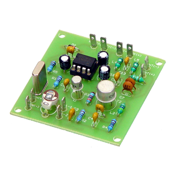
FreeBytes RadioKit-120 Manual de montagem e funcionamento - Página 2
Procurar online ou descarregar pdf Manual de montagem e funcionamento para Transcetor FreeBytes RadioKit-120. FreeBytes RadioKit-120 11 páginas. 20μ cw ham radio transceiver kit

Thank you for buying RadiØKit-1, a ham radio CW transceiver for the 80M
(RadiØKit-180), the 40M band (RadiØKit-140) or the 20M band (RadiØKit-120).
RadiØKit-1 is part of a series of electronic kits that we offer not only to radio
amateurs who want to discover the joy of building their own equipment, but
also to all the electronics DIY enthusiasts who like to construct various devices
for everyday use or just for the fun of it.
The kit is based on the famous Pixie transceiver introduced many years ago.
The design was improved over the years and still catches the interest of many
radio amateurs over the world due to it's simplicity, satisfying performance and
ease of construction.
RadiØKit-1 incorporates additions and improvements that we will discuss later
on. The circuit board is constructed by FR-4 material, the placement of the
components is silk screened on the top side. All the copper traces on the
bottom side are solder masked to prevent short circuits and accidental bridging
between conductors. All component holes are already drilled. There are also
four drilled holes for placing the board inside a box using appropriate screws
and spacers. The components that are used for RadiØKit-1 are of the highest
quality. All the resistors are metal film 1% type. The capacitors are of the
MLCC type except for the electrolytic ones that are mini sized 85°C types and
two 820pF capacitors that are ceramic. The inductors used are resistor type
and provide high performance and minimum space usage. The famous
2N2222A and 2N3866 transistors are used in order to achieve a little bit more
output power.
DC voltage is applied by a 9 Volt battery (not included) or a 9V to 12V power
supply (not included). The output RF power produced is approximately 160mW
with a 9V battery or 250mW with a 12V power supply. You only need to
connect the battery, a Morse key, an earphone or small speaker and an
appropriate antenna to have a fully working ham radio transceiver. RadiØKit-1
comes in three flavors. One for the 80M CW radio amateur band, one for the
40M band and one for the 20M band.
CIRCUIT DIAGRAM DESCRIPTION
OSCILLATOR
The main oscillator of RadiØKit-1 is a classic colpitts circuit and is comprised by
the components Τ1, R1, R2, C1, C2, C3, C12 and the crystal (XTAL) for either
80m, 40m or 20m band (one of the three crystals is supplied according to the
model). R1 is used only when the power is applied to kickstart the oscillations.
C1 and C2 are a capacitive voltage divider and provide positive feedback from
the emitter of T1 back to it's base. The crystal behaves like an inductor and
sets the frequency of oscillation which can be slightly altered by C12. R2 is the
load resistor of the oscillator and sets it's output impedance. It also provides a
small amount of negative feedback at the emitter of T1 making the operation
of the oscillator more stable. The oscillator is active during both reception and
transmission of the transceiver. C3 is used to couple the output of the oscillator
to the base of T2 which functions as an amplifier during transmit and as a
