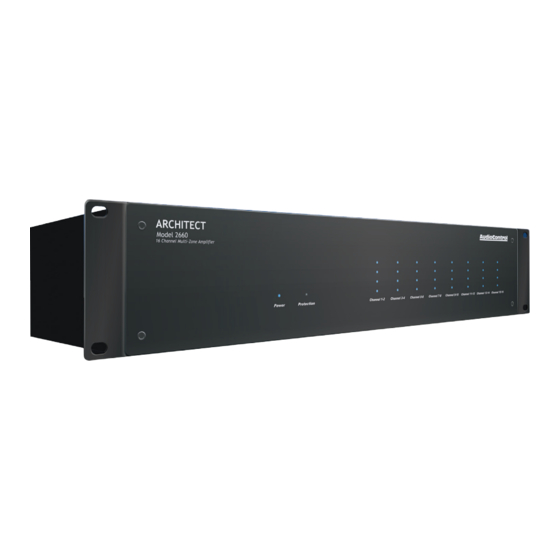
AudioControl ARCHITECT MODEL 2660 Manual de instalação - Página 8
Procurar online ou descarregar pdf Manual de instalação para Amplificador AudioControl ARCHITECT MODEL 2660. AudioControl ARCHITECT MODEL 2660 15 páginas. 16 channel multi-zone power amplifier

Rear Panel continued
2
3
5
1
4
The trigger input is biased towards
ground. This keeps the unit in standby
when nothing is connected.
If you are not using master trigger-
ing, then you must install a short
wire link from the +12V output
to the trigger input. To put the unit into
standby, remove the link.
Wire Link
To trigger ON with a contact closure:
Connect the contact closure between
+12V and Trigger Input
To trigger OFF with a contact closure:
Connect a 1 kΩ resistor between +12V
and Trigger Input
Connect the contact closure between
Trigger Input and GND
14
7
8
9 10
11
6
13
12
To use an external 12V trigger:
Connect the external ground to the
Architect Model 2660 GND
Connect the external +12V output
voltage to the Architect Model 2660
Trigger Input
Bus A and B Sections
7. BUS A Input – This S/PDIF digital input
uses a standard RCA coaxial connec-
tor.
The digital signals are converted into
two analog channels by the unit's fine
internal digital to analog converters.
The two audio channels are then avail-
able to any zone that has its DIP switch
4 set to Bus A (left), and switch 3 set to
Bus (right).
The Signal Present LED lights when-
ever a signal is present at the Bus A
input.
8. BUS B Input – This pair of standard
RCA coaxial connectors accepts
line-level analog audio signals from
source equipment such as CD players,
DVD players, and MP3 players etc. The
two audio channels are then available
to any zone that has DIP switch 4 set
to Bus B (right), and switch 3 set to Bus
(right).
The loop outputs allow a copy of the
Bus B analog inputs to be sent out and
shared with other units. The loop outs
are directly wired internally to the Bus
B analog inputs, and will pass signals to
other units, even if the host unit is pow-
ered off.
The Signal Present LED lights whenever
a signal is present at the Bus B input.
Zone Section
(all details are the same for each zone)
9. Zone Level Control – This control sets
the output level for the zone, inde-
pendent of the levels of all the other
zones. Turn the controls with your
fingers to make the adjustments. You
may have to readjust the level if you
change the source to that zone, from
Bus A, Bus B, or Local.
10. DIP Switches – These five switches
allow each zone to be set up individually:
DIP Switch Function Table
Switch
Label
Left (OFF)
1
Mono
The zone is Stereo
2
PFM 40 Hz
The 40 Hz high pass
filter is off
3
Local/BUS
The zone is using the
Local input
4
BUS A/B
The zone is using the
BUS A input (S/PDIF), if
switch 3 is set to BUS
5
Signal
Signal sense is off
Sense
Rear Panel continued
Switch 1. MONO: Left is Stereo, Right is
Mono, and the inputs are summed.
Switch 2. PFM 40 Hz – This is a high-pass
filter to reduce signal levels below 40
Hz that are not reproduced well by
small speakers. Left is off, Right is on.
Switch 3. LOCAL/BUS – Left selects the
Local input as the zone's input, Right
selects the BUS Input, either A or B,
depending on the position of switch 4.
Switch 4. BUS A/BUS B Selector – This
switch is only active when switch 3 is
set to BUS (right). Left selects BUS
A (S/PDIF) as the zone's input, Right
selects BUS B (Analog).
Switch 5. Signal Sense – This switch
controls whether the zone is always
active when the master 12V trigger is
active, or if the zone stays in standby
until a signal is sensed. If signal sense
is on (switch right) the zone will stay in
standby until an audio signal greater
than 5 mV is detected. The zone will
remain active whenever a signal is
present. After two minutes with no
signal detected, the zone will return to
standby.
Right (ON)
The zone is Mono
The 40 Hz high pass filter
is on
The zone is using the BUS
input selected by switch 4
The zone is using the BUS
B input (Analog), if switch
3 is set to BUS
Signal sense is on
ARCHITECT
™
Model 2660
Installation Manual
15
